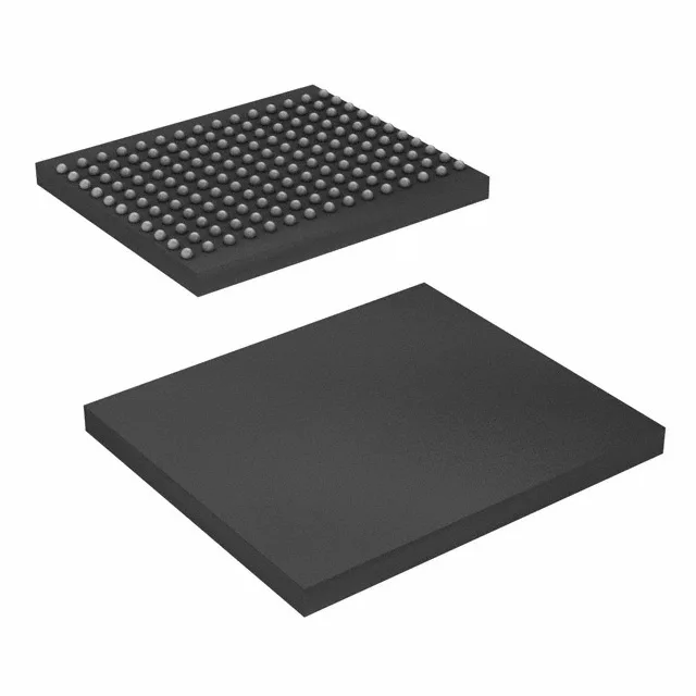
400 MHz DDR II+ SRAM for high-throughput line cards
This part targets networking, telecom, and high-end computing applications where back-to-back read/write throughput and zero bus-turnaround dead cycles are critical — exactly the class of SRAM used in packet buffers, lookup tables, and queue managers on line cards and base stations.
What the 400 MHz clock and 2M x 36 organization mean for the BOM
The 400 MHz clock rate on a DDR II+ (Double Data Rate) interface means the memory delivers two data transfers per clock cycle, yielding an effective data rate of 800 MT/s per pin. For a 36-bit-wide word, that translates to a peak bandwidth of 28.8 Gbit/s — enough to keep a high-speed ASIC or FPGA fed without wait states. The 2M x 36 organization is a 72 Mbit density, but the 36-bit bus width is the key fit parameter: it matches the natural word width of many network processors and FEC engines.
Industrial temperature grade — deployment environment
The 1.7V to 1.9V core supply aligns with low-power 1.8V logic families common in modern FPGAs and SoCs. The 165-FBGA (13x15 mm) footprint is a standard ball grid array for this density class; the 1.0 mm ball pitch (typical for a 13x15 FBGA) requires careful PCB routing but is manageable with a 4-layer board if the via fanout is planned for.