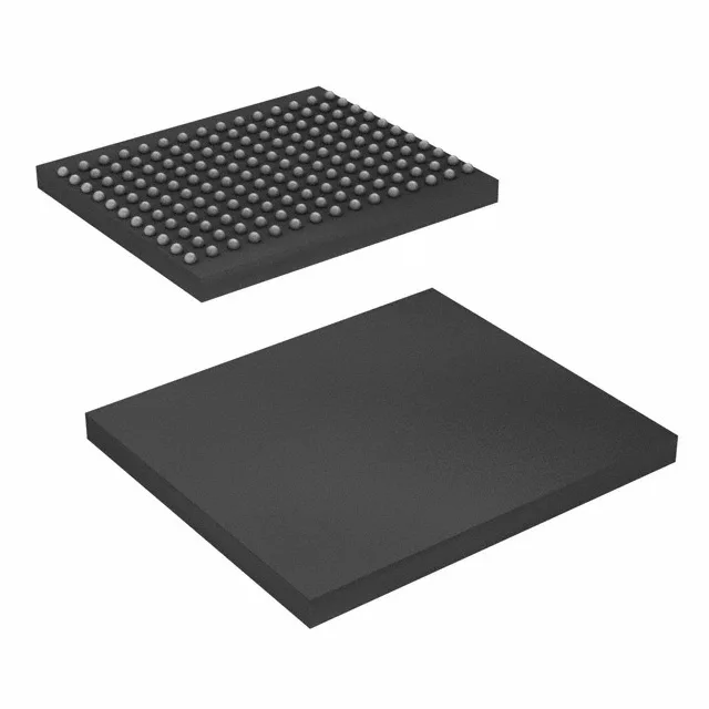
72 Mbit QDR II SRAM at 300 MHz — what the bus sees
The ninth bit per word gives you a parity lane for each byte — common in networking line cards and test equipment where a single-bit error on a buffer read stalls the pipeline. Clocked at 300 MHz, the QDR II architecture delivers back-to-back read and write on separate buses, so the controller never stalls for bus-turnaround dead cycles the way a common DDR SRAM does.
300 MHz clock — timing closure and signal integrity
At 300 MHz the clock period is 3.3 ns. The QDR II interface is source-synchronous with a separate read clock and write clock, so the FPGA or ASIC controller must match the PCB trace delay within a few hundred picoseconds. The 165-FBGA (13x15) package keeps the signal path short, but the board layout needs controlled-impedance traces and matched-length routing between the memory and the controller.