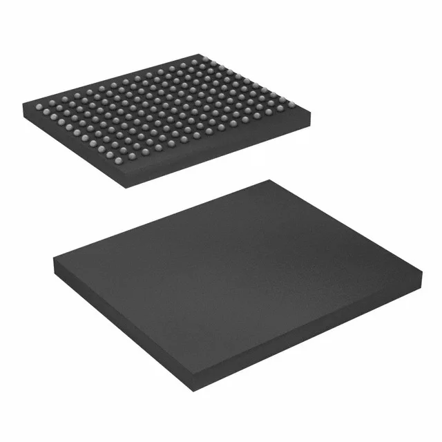
What this QDR II SRAM does in the system
The 300 MHz clock rate delivers back-to-back read/write throughput without dead cycles, which is the defining advantage of the QDR II architecture over conventional burst SRAM. This part is designed for high-bandwidth data-path applications such as network switches, line cards, and packet buffers where low-latency, predictable memory access is critical.
300 MHz clock and the bus margin decision
The 300 MHz clock frequency is the headline rating that determines whether this SRAM can keep up with a 300 MHz FPGA or ASIC memory controller. At 300 MHz, the QDR II interface eliminates the bus-turnaround dead cycles of NoBL or pipelined SRAM, so the effective data rate is 600 million transfers per second per 36-bit port. For a system architect, the trade-off is that the 1.7V to 1.9V supply rail must be clean and well-regulated—ripple or droop beyond that window will close timing margins on the address and control inputs.
The CY7C1515KV18-300BZCT comes in a 165-ball LBGA (supplier device package 165-FBGA, 13x15 mm body). This is a fine-pitch BGA, so the PCB requires a via-in-pad or microvia process for the inner rows. The Tape & Reel (TR) shipping medium is standard for pick-and-place assembly; the moisture sensitivity level (MSL) is not listed here, but BGA packages of this density typically carry MSL 3 or higher, so a bake before reflow is prudent if the sealed bag has been opened past the floor-life window.