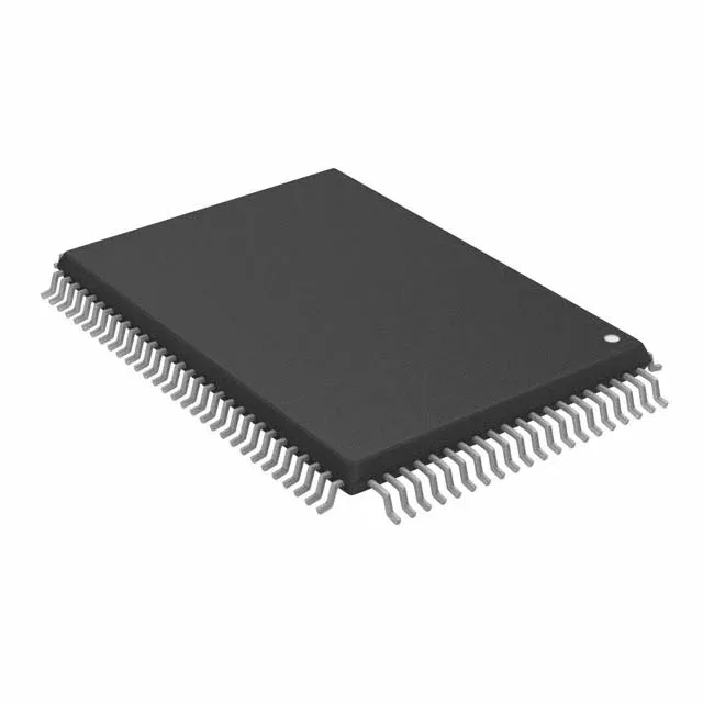
Infineon Technologies CY7C1462KV25-200AXCT — Memory (DRAM / SRAM / Flash / EEPROM)

CY7C1462KV25-200AXCT 36Mbit NoBL SRAM, 200 MHz, 3.2 ns

MPNCY7C1462KV25-200AXCT
Active

Cypress CY7C1462KV25-200AXCT, NoBL™ series, 36Mbit Synchronous SRAM, 2M x 18 organization, 200 MHz clock frequency, 3.2 ns access time, 2.375V–2.625V supply, 100-LQFP, 0°C–70°C.

$84.1750Ref. price · indicative, final on quote
Independent supplier — new & surplus stockAuthenticity-screened · ESD-safe packingListing updated Aug 2026

Specifications

CY7C1462KV25-200AXCT specifications
ParameterValue
SeriesNoBL™
Memory typeVolatile
MountingSurface Mount
Supply voltage2.375V ~ 2.625V
Clock frequency200 MHz
Memory interfaceParallel
Operating temperature0°C~70°C(TA)
PackageTape & Reel (TR)
TechnologySRAM - Synchronous, SDR
Access time3.2 ns
Memory size36Mbit
Memory formatSRAM
Case100-LQFP
Memory organization2M x 18

Product details

36 Mbit NoBL SRAM at 200 MHz — what it brings to the bus

It clocks at 200 MHz with a 3.2 ns access time, meaning back-to-back reads and writes can run every cycle without dead cycles on the bus — the NoBL pipeline eliminates the turnaround latency typical of conventional synchronous SRAMs. This part targets high-throughput data buffering in networking switches, test equipment, and baseband processing where every clock cycle of throughput matters.

2.5 V supply rail — plan the power tree accordingly

The supply range is 2.375 V to 2.625 V, a dedicated 2.5 V rail. The I/O levels match the core supply, so any interface to a 3.3 V controller requires external level translation on address and control lines.

Not suited for outdoor, automotive, or industrial enclosures where ambient temperatures exceed 70°C or drop below freezing.

Frequently asked questions

What is the access time of CY7C1462KV25-200AXCT?

The access time is 3.2 ns, measured from the clock edge to data valid. At a 200 MHz clock (5 ns period), the 3.2 ns access leaves 1.8 ns of setup margin before the next clock edge — enough for most FPGA and ASIC interfaces, but timing closure should be verified with the actual PCB trace delay and I/O buffer skew.