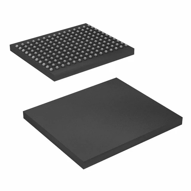
36 Mbit DDR II SRAM — 250 MHz pipeline buffer
It clocks at 250 MHz on a parallel interface, delivering back-to-back read/write throughput without dead cycles — the DDR II architecture transfers data on both clock edges, effectively doubling the bandwidth per pin.
1.8 V core rail — dedicated regulator required
The 250 MHz clock rate means the supply noise budget is tight; a standard LDO with 50–70 dB PSRR at 1 MHz should hold it. The parallel interface is 18-bit wide, so the PCB trace matching across the data bus matters for timing closure at this speed.
165-ball FBGA — rework and layout notes
Housed in a 165-ball FBGA measuring 13x15 mm. Fine-pitch BGA — expect 1 mm ball pitch, which is manageable with standard PCB fab processes (4-mil trace/space). Route the 18 data lines plus address and control on inner layers; use microvia or through-via escape depending on layer count. Hot-air rework is possible with a bottom-side preheat profile; a stencil aperture reduction to 80–85% of the pad diameter helps prevent solder bridging.
This rules out outdoor telecom cabinets, automotive under-hood, or factory floor without HVAC.