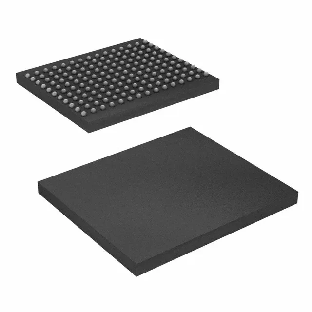
DDR II SRAM for high-throughput data buffers
It clocks at 250 MHz using a double-data-rate interface, meaning data transfers on both edges of the clock for an effective 500 MT/s bandwidth on an 18-bit bus.
250 MHz clock — timing margin in a DDR interface
At 250 MHz the DDR II core delivers a 4 ns clock period, but the double-data-rate nature halves the data valid window to roughly 2 ns. The part's internal pipeline and output hold times are specified for that window, so the FPGA or ASIC controller needs to meet setup/hold at the SRAM pins without excessive PCB trace skew. If the design already runs a 250 MHz DDR controller, this part drops in; if the controller tops out at 200 MHz, a slower speed grade saves cost.
The PCB layout should place a 0.1 µF ceramic cap within 2 mm of each VDD pin, plus a 10 µF bulk cap per quadrant of the 165-FBGA footprint. The 165-FBGA (13x15) package uses a 1.0 mm ball pitch — no via-in-pad required, but the escape routing needs at least two signal layers.
If the system sees -40°C or +85°C, look at the industrial-temperature variants in the same Cypress DDR II family.
For new designs this is a safe selection; for production builds the supply channel is stable through independent distribution.