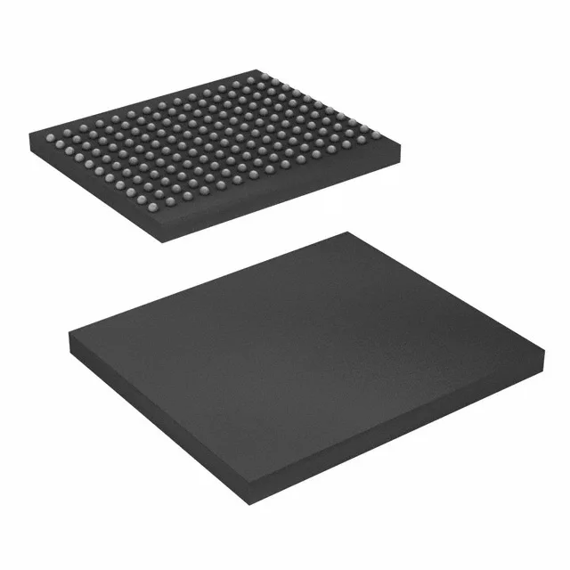
36Mbit QDR II SRAM at 300 MHz — what it does for the bus
It clocks at 300 MHz on a parallel interface, delivering back-to-back read and write operations on separate data ports without dead cycles — the QDR II bus-turnaround advantage that matters for high-throughput packet buffers, lookup tables, and cache in networking, telecom, and test equipment.
300 MHz clock — timing margin in the signal-integrity budget
At 300 MHz the cycle time is about 3.3 ns. That puts pressure on PCB trace-length matching and on the controller's output-hold timing. The QDR II architecture helps by separating read and write data buses, so you avoid the bus-turnaround penalty that cuts throughput on common-I/O SRAMs. Plan for controlled-impedance routing and on-die termination if the controller supports it — the 165-ball FBGA (13x15 mm) keeps the package inductance low, but the board layout still needs care.
That means Cypress has announced end-of-life for this specific speed and package variant. If your design depends on this exact order code, the window for final purchases is closing. For new designs, evaluate the current QDR II+ or QDR IV generations from Cypress (now Infineon) — but verify pin-compatibility and controller support, because package and timing may differ.
The 200 mV tolerance means your regulator needs tight load regulation — a 1.8 V nominal rail with ±3% is fine, but a 1.8 V rail that droops to 1.65 V under transient load will violate the minimum. Place a 0.1 µF ceramic per supply pin and a 4.7 µF bulk cap near the BGA's power balls. The 165-FBGA has a 13x15 mm footprint with a 1.0 mm ball pitch — standard via-in-pad or microvia process recommended for routing out the inner balls.