QDR II SRAM at 250 MHz — what drives the choice
It runs at a 250 MHz clock, delivering back-to-back read and write transactions on every clock edge with no dead cycles between bus turnarounds — the hallmark of QDR II. This part targets high-throughput datapaths in networking equipment, test instrumentation, and FPGA-based processing where the memory interface must keep pace without arbitration stalls. The 1.7V to 1.9V supply range places it on a dedicated 1.8V rail, separate from the 3.3V or 2.5V I/O bank of the host controller. Designers should budget a local LDO or switching regulator for this rail, as sharing a 1.8V plane with other peripherals may introduce noise that eats into the timing margin at 250 MHz.
250 MHz clock — bus timing and signal integrity
At 250 MHz the clock period is 4 ns, and the QDR II interface samples data on both edges, so the effective data rate is 500 MT/s per pin. The 18-bit data bus delivers 9 Gbit/s aggregate bandwidth. Signal-integrity closure on the PCB — trace-length matching, controlled impedance, and minimal stub length — becomes critical at this rate. The 165-ball FBGA package (13x15 mm) uses a fine-pitch ball array that demands a multi-layer PCB with buried vias for fan-out; a two-layer board will not support this interface cleanly. Compared to the 300 MHz sibling CY7C1415KV18-300BZXC, the 250 MHz part trades 50 MHz of clock speed for a 2M x 18 organization instead of 1M x 36. The 2M x 18 width suits designs that process 18-bit words (e.g., 18-bit ADC data or 16-bit + parity), while the 1M x 36 variant fits 36-bit wide buses. Neither is a drop-in replacement — the pinouts differ due to the data-width change.
Infineon lists the CY7C1412KV18-250BZXC as Active.
Package and temperature — board-level fit
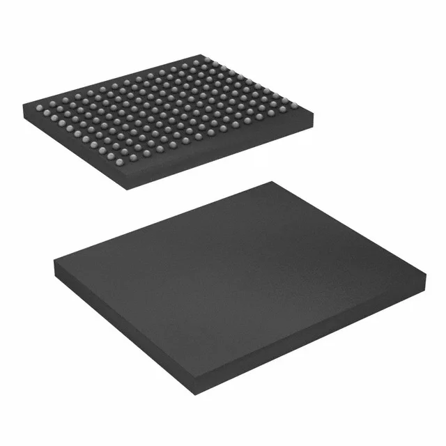
The 165-ball FBGA (13x15 mm) is a surface-mount BGA. Reflow profile follows standard lead-free solder profiles;.