Memory organization and timing at 250 MHz
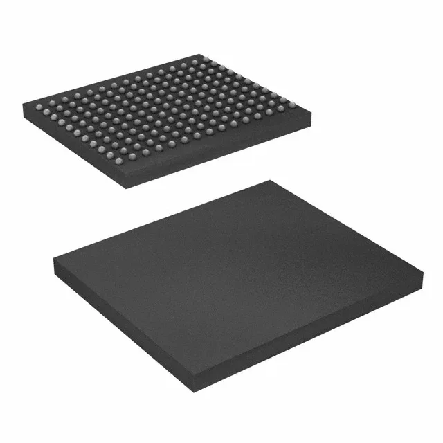
The CY7C1411KV18-250BZC: Organized as 4M x 8, the part delivers 36 Mbit of volatile SRAM using a synchronous QDR II architecture. The 250 MHz clock rate supports a double-data-rate interface — data transfers on both edges, yielding an effective throughput of 500 MT/s per I/O pin. The parallel memory interface requires a controller that implements the QDR II protocol, including separate read and write data ports.
Package footprint and board integration
The surface-mount footprint requires a multi-layer PCB with controlled impedance traces for the QDR II bus — the 250 MHz edge rates demand careful signal-integrity simulation, especially for the clock and strobe pairs. Supplied in tray format, the parts are suitable for pick-and-place assembly. The FBGA land pattern should follow the JEDEC MO-216 standard for 165-ball arrays.