18 Mbit synchronous SRAM at 167 MHz — the speed-grade decision
The CY7C1372KV33-167AXC: That access time is the window from clock edge to data valid on the bus; at 167 MHz the cycle time is 6 ns, so the 3.4 ns access leaves 2.6 ns of setup and hold margin for the controller. If your FPGA or ASIC memory controller has a tighter input timing budget, this part's speed grade is the one you want. The commercial temperature range (0°C to 70°C) suits networking equipment, test gear, and base stations that live indoors; for extended-temp or automotive requirements this is not the right variant.
NoBL pipelined architecture — what it means for bus utilisation
NoBL (No Bus Latency) means the SRAM can accept a new read or write address on every clock cycle without dead cycles between operations, as long as the pipeline depth is respected. A standard synchronous SRAM inserts a turnaround cycle when switching from read to write; NoBL eliminates it, so the bus stays at 100 % utilisation at the full 167 MHz clock rate. For a cache or packet buffer that alternates read and write access, this lifts throughput without raising the clock. The 18-bit-wide data bus (1M x 18) maps naturally to a 16-bit word plus two parity/ECC bits, or to an 18-bit DSP word. The parallel interface uses the standard synchronous SRAM control set — chip enable, write enable, output enable, byte write selects — so it drops into existing controller designs with minimal glue logic.
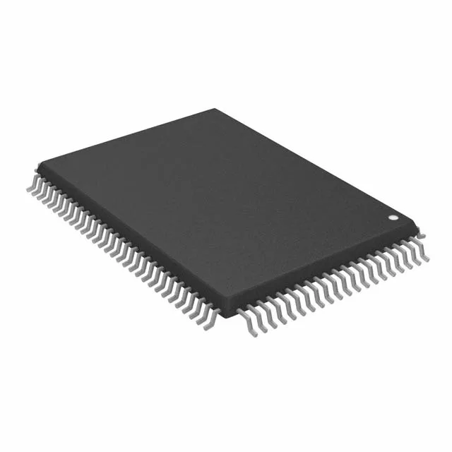
Housed in a 100-TQFP (14x20 mm) with 0.5 mm pitch — a standard fine-pitch QFP that routes on a 4-layer board without microvias. The exposed pad on the bottom side (if present on this variant) should be stitched to the ground plane with thermal vias; the datasheet's recommended land pattern is the reference for the solder-paste stencil aperture. Surface-mount only; the tray packaging is typical for volume assembly. Confirm the MSL rating on the reel or tray label before opening the sealed bag.