What the 200 MHz clock and 3 ns access mean for your bus timing
The CY7C1370KV25-200BZC is a 18 Mbit synchronous SRAM from Infineon's NoBL™ (No Bus Latency) series, organized 512K x 36. The 200 MHz clock rate sets the maximum data transfer cadence on the parallel bus — each clock edge can initiate a new read or write cycle without dead cycles between back-to-back transactions, which is the defining characteristic of the NoBL™ pipeline. The 3 ns access time is the interval from clock edge to data valid on the output pins. At 200 MHz the clock period is 5 ns, so 3 ns access leaves 2 ns of setup margin before the next clock edge — enough headroom for most FPGA or ASIC interfaces running at this speed, but the trace-length matching and board impedance become critical to hold that margin across temperature.
Supply rail tolerance and temperature grade — where this part fits
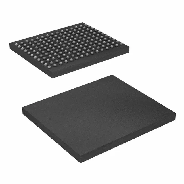
The core supply range is 2.375 V to 2.625 V, a tight 250 mV window that requires a regulated rail — a 2.5 V LDO or switching converter with <1% set-point accuracy. The 165-ball FBGA package (13x15 mm body,) uses a 1.0 mm ball pitch — standard for this density. The PCB fan-out requires at least four layers to route the 36 data lines plus address and control signals without excessive via stubs that would degrade signal integrity at 200 MHz.