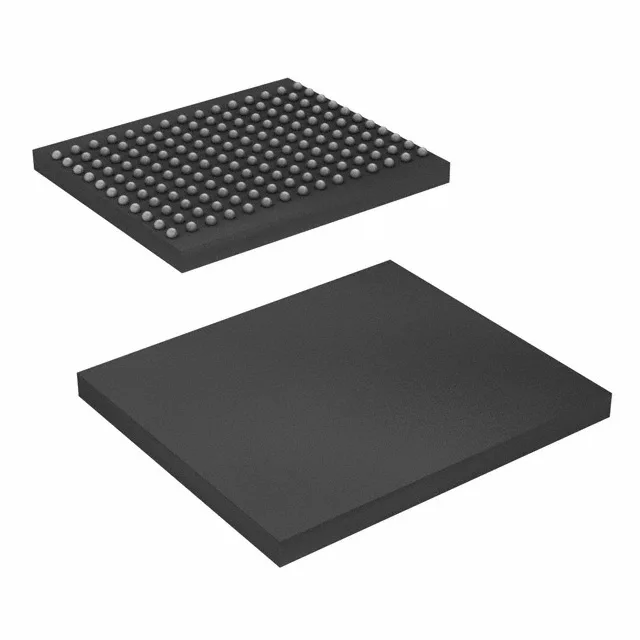
165-FBGA footprint and board integration
The CY7C1354D-200BZC: The supply voltage range is 2.4 V to 2.6 V, so a 2.5 V rail regulated to ±2 % keeps the core within spec across load transients. Decoupling capacitance at the package balls, not just at the board edge, controls the switching noise from the 200 MHz clock.
200 MHz synchronous pipeline and 3.2 ns access
The 200 MHz clock drives a synchronous SDR pipeline — address and control are registered on the rising edge, and the 3.2 ns access time is the delay from clock edge to data valid at the output register. The 36-bit wide data bus (256K x 36 organization) maps naturally to a 32-bit processor bus with a 4-bit parity or ECC nibble; the extra width absorbs the check bits without a second device. The parallel interface means no serialisation latency, but the bus timing must match the controller's AC parameters at 200 MHz.
Commercial temperature range and supply tolerance
The 2.4 V to 2.6 V supply window is tighter than a typical 2.5 V ±5 % rail; a ±2 % regulator (2.45 V to 2.55 V) provides margin against the IR drop across the PCB. The SRAM is volatile and synchronous — data is lost at power-down and the register contents are undefined until the clock stabilises after power-up.