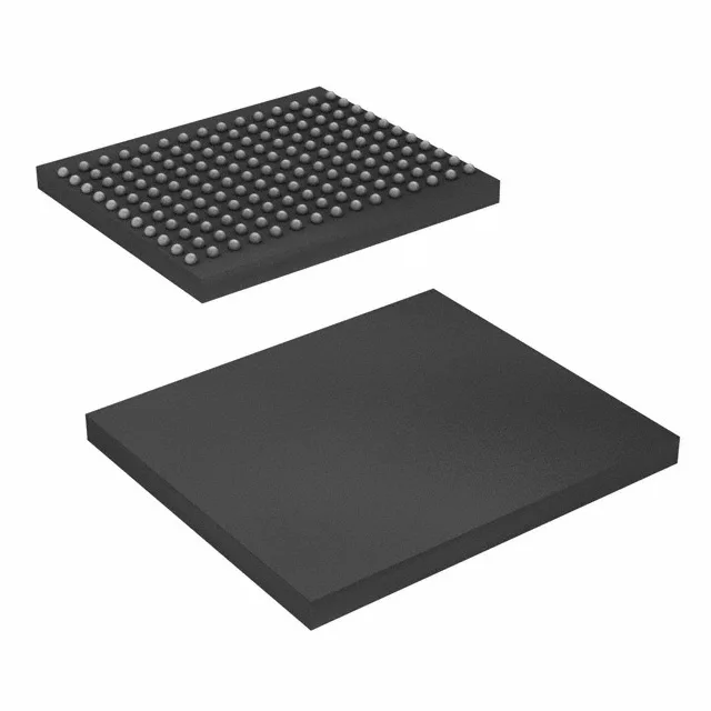
The CY7C1312CV18-167BZI: The 165-FBGA package with a 13x15 mm body and 1.0 mm ball pitch demands a multi-layer PCB with controlled impedance for the QDR II interface traces. Decoupling capacitors should be placed close to each supply ball pair; the 1.7V-1.9V core rail requires low-ESR ceramic caps at both the package perimeter and at the board power entry. The 165-ball array has no center thermal pad; junction-to-board thermal resistance is managed through the signal balls and the board copper plane.
Memory architecture and timing considerations
As a QDR II device, the CY7C1312CV18-167BZI provides separate read and write data ports, each 18 bits wide, allowing simultaneous read and write operations at the full 167 MHz clock rate. The 1M x 18 organization yields 18 Mbit total density, with the 18-bit word width suited for 18-bit DSP datapaths or as a 2-byte-wide buffer with parity. The 167 MHz clock frequency gives a 6 ns cycle time for each port — read and write operations each complete within one clock cycle. Timing closure on the QDR II bus requires matched trace lengths between the controller and the SRAM for all address, data, and control signals, with propagation delays kept within 50 ps skew to meet the setup/hold windows.