18 Mbit DDR II+ SRAM at 450 MHz — bus bandwidth for high-throughput buffers
It clocks at 450 MHz over a parallel interface, delivering back-to-back read/write throughput without the dead cycles that plague conventional burst SRAM.
450 MHz clock — timing closure and bus margin
At 450 MHz the clock period is roughly 2.22 ns. The DDR II+ interface transfers data on both edges, so the effective data rate per pin is 900 MT/s. That puts tight demands on the controller's output hold time and the board's trace-length matching. The 36-bit data bus at this speed typically needs a source-synchronous clocking scheme with per-byte DQS strobes — the controller must support that protocol, not just a generic synchronous SRAM interface. If your FPGA or ASIC memory controller is rated for 400 MHz or lower, this part is a speed-grade mismatch; budget the timing analysis before committing the layout.
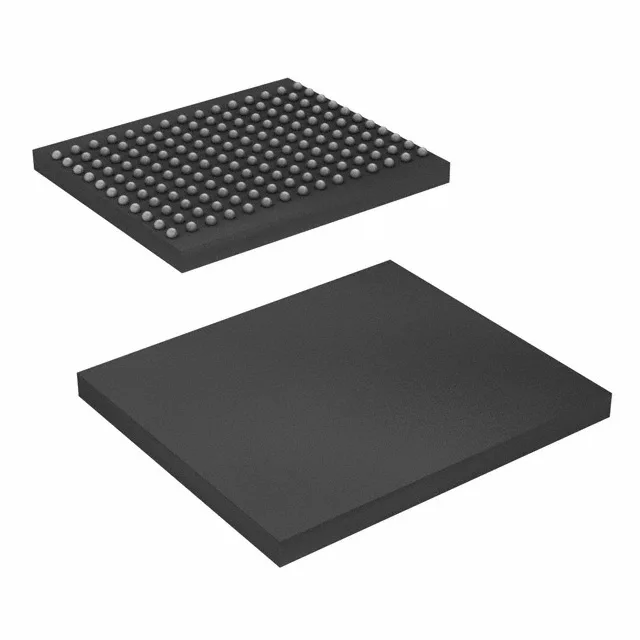
The 165-ball FBGA (13 x 15 mm) uses a 1.0 mm ball pitch. That is a standard BGA footprint that four-layer PCBs can route with via-in-pad or dogbone fanout. The supplier device code 165-FBGA (13x15) tells you the exact ball map — order the Cypress package drawing before laying out the escape pattern. No heatsink is required at commercial temperature and 1.9 V max supply; the package's thermal pad (if exposed) should be stitched to a ground plane with at least nine vias for adequate heat transfer.
It belongs in indoor equipment — servers, switches, base stations, test gear — not in an engine bay, rooftop enclosure, or unheated warehouse. If your system sees -20°C startup or 85°C internal air, step up to the industrial-temperature variant in this family (BZ suffix vs. BZ).