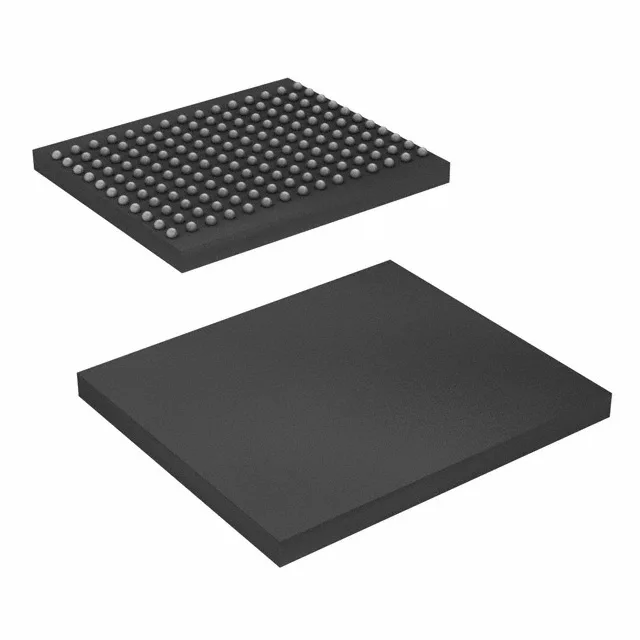
The Infineon CY7C1150KV18-400BZC is a 18 Mbit synchronous SRAM using a DDR II+ (double-data-rate, second-generation-plus) interface, organized as 512K words by 36 bits. It clocks at 400 MHz, delivering back-to-back read/write transactions on every clock edge — the DDR II+ protocol eliminates dead cycles on the bus, so the controller sees full-rate throughput without wait states. This part targets high-bandwidth, latency-sensitive buffers: network switch lookup tables, telecom line-card packet memories, and high-end FPGA co-processing where a wide 36-bit word matches internal data-path widths.
400 MHz clock — the bus timing reality
At 400 MHz the DDR II+ interface toggles data on both edges, so the effective data rate is 800 MT/s per pin. For a 36-bit-wide bus that's 3.2 GB/s peak. The 165-ball FBGA (13x15 mm) keeps signal lengths short, but the layout engineer needs to match trace lengths within a few hundred mils and keep the clock-to-strobe skew tight.
That's a ±5.6% window — tighter than a typical 1.8 V ±10% LDO. If the rail droops below 1.7 V during a burst read, the SRAM may lose data or corrupt the bus. Pick a regulator with at least 1% initial accuracy and good transient response; a 1.8 V fixed-output LDO with 300 mV dropout at the load current works. Don't pull this rail from a shared 1.8 V supply that also feeds noisy digital logic — the SRAM's supply needs its own local decoupling.
For BOM planning, this part presents no single-source risk; Infineon continues to manufacture it.