Crystal selection and BOM fit
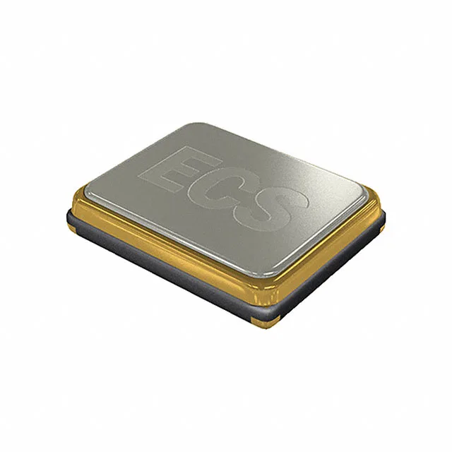
The ECS-294.912-18-30-JEM-TR: The ECX-53 series 29.49 MHz fundamental-mode crystal drives the clock input for MCUs, communication modules, and timing reference circuits in consumer and industrial electronics. Load capacitance of 18 pF is the design target for the external load network — the PCB trace capacitance plus the two series caps must sum to this value for the oscillator to hit nominal frequency at first power-up. Frequency stability of ±50 ppm covers the total drift budget across the operating temperature window of -20°C to 70°C. Tolerance at room temperature is ±20 ppm — that is the initial-set accuracy the firmware clock and communication baud-rate dividers see before temperature moves the crystal off nominal. ESR is rated at 30 Ω. High ESR relative to a low-impedance MCU oscillator pin means the crystal draws more power from the Pierce oscillator startup circuit — the oscillator must provide sufficient drive level to overcome the losses. Most modern MCUs are comfortable with 30 Ω at 29.49 MHz, but confirm the oscillator drive strength in your MCU datasheet if the design runs from a coin cell or very low-power sleep mode.
Footprint and thermal profile
Solder joint reliability is governed by the pad footprint opening and the paste volume; a pad mask 60–70% of the package width typically gives the right fillet. Maximum seated height is 1.40 mm. That keeps it clear of most low-profile enclosures, but for portable or stacked-module designs confirm the housing pocket depth — a crystal that sits proud of the PCB top surface needs clearance above the package, not just the board.
Sourcing and lifecycle
Active lifecycle per ECS Inc. — this line is not flagged for discontinuation or NRND. Quoted to order against BOM quantity through independent distribution channels with full lot traceability confirmed at RFQ.