Crystal selection parameters for timing-critical designs
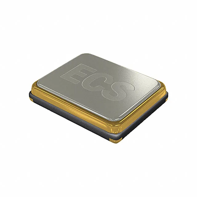
The ECS-286.3-18-33-JEM-TR: 18 pF load capacitance specifies the external capacitors the MCU or SoC must drive on either side of the crystal — many chipsets include internal load capacitance and allow the designer to trim the effective load by changing the external capacitors, so the 18 pF figure is the starting point, not a hard requirement on the board. ±50 ppm frequency stability covers the total drift across the operating temperature band of -20 °C to 70 °C, while the ±20 ppm tolerance describes the initial deviation from nominal at 25 °C — a well-sourced crystal for USB video timing or embedded audio should be measured on a frequency counter before board assembly to catch any initial tolerance drift that could push the baud-rate or sample-rate out of the expected window. 40 Ohm ESR limits the drive-level capability of this crystal — most microcontroller datasheets specify a maximum drive level in microwatts, and staying below it prevents the crystal from fracturing over long field life; the 40 Ohm ESR is modest enough for standard MCU oscillator circuits but rules out high-drive-level oscillator designs. Commercial temperature grade -20 °C to 70 °C means this part belongs in office equipment, consumer electronics, indoor display panels, and any enclosure that does not see open-air outdoor or industrial ambient — if the end-equipment runs near a heat source or in an unconditioned space, a wider-grade crystal with -40 °C capability is the right call.