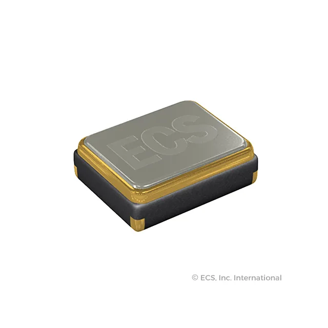
Thermistor-compensated 26 MHz crystal for timing circuits
The ECS-260-7-37TC-CZY-TR is a 26 MHz fundamental-mode crystal with an integral thermistor, built in the ECX-1637TC series. The thermistor enables the oscillator loop to apply temperature-compensated drive — critical for applications where frequency drift across the -30°C to 85°C operating window must stay within the total budget. Load capacitance is specified at 7 pF, which sets the resonant frequency when the crystal is placed in the Pierce or similar topology circuit; mismatched loading shifts the output off the 26 MHz nominal.
Frequency budget: stability plus tolerance
±10 ppm tolerance at 25 °C plus ±12 ppm stability across temperature gives a worst-case total deviation of ±22 ppm from nominal — a ±572 Hz window at 26 MHz. For a UART baud-rate crystal or a reference clock in a sensor node, that is within most ±0.025 % accuracy budgets. The tighter the total budget, the more critical it is to hit the 7 pF load spec on the PCB, since capacitance trimming is the usual compensation lever when the oscillator circuit strays from nominal.
4-SMD package and board integration
Four no-lead terminations on the sides provide both the electrical connection and mechanical anchor — reflow solder to the pad pattern, no through-hole leads. ESR is 50 Ω; the driving circuit should be checked against the maximum drive level the crystal can tolerate to avoid long-term frequency ageing. The part ships in tape-and-reel or cut-tape packaging.