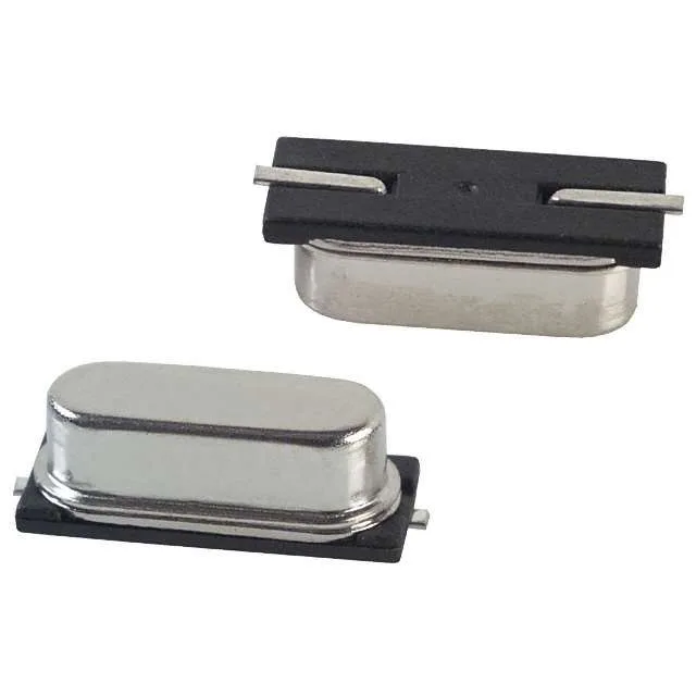
Precision timing at 20.3563 MHz — what the tolerance stack means
The ECS-203.563-CDX-0375: The 20.3563 MHz fundamental-mode crystal carries a combined accuracy budget of ±50 ppm when you add the ±20 ppm initial tolerance and ±30 ppm stability drift over temperature — for most microcontroller clock trees this sits comfortably within the ±40 ppm window the MCU expects at startup, but a design running UART baud at 115.2 kBd should check that the crystal's cumulative error does not push the baud rate out of the ±1.5% receiver tolerance band. 12 pF load capacitance is the spec the oscillator circuit needs to present — if the MCU's internal load caps are fixed, the external crystal load must match 12 pF to hit the rated frequency; if the MCU uses external trimmable caps, budget them to bring the total including stray capacitance to 12 pF. 30 Ω ESR maximum means the crystal draws more drive power for a given load than a low-ESR TCXO would — the oscillator startup current is bounded by the MCU's internal transconductance and the crystal's ESR, so a 30 Ω unit starts reliably at 3.3 V on a typical Cortex-M layout, but a long oscillator trace or high-ESR layout variant can miss the startup margin.
HC-49/US SMD — the standard footprint that keeps the pick-and-place happy
HC-49/US in the SMD (gull-wing) variant is the most widely supported crystal package in the industry — any standard reel-fed pick-and-place head handles the 11.40 mm x 4.80 mm body without custom nozzle changes, and the gull-wing leads reflow with a standard Sn96.5/Ag3/Cu0.5 profile without special thermal delta requirements. Seated height of 4.30 mm max keeps it clear of most board-level underfill and conformal coat requirements — a low-profile crystal sitting above the MCU clock input trace on a two-layer board is a clean layout without the thermal pad or ground plane complications that come with hermetic ceramic packages.