Clamping voltage and peak current — the surge survival numbers
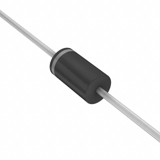
The 1.5KE75A-HF: The 103 V maximum clamping voltage at 14.56 A (10/1000 µs pulse) is the hard ceiling: any transient that would push the voltage above this level is shunted through the diode. The 1500 W rating is the product of clamp voltage and peak current at that pulse width — a shorter pulse (8/20 µs) allows higher peak current, but the 10/1000 µs rating is the standard telecom and industrial benchmark. The 64.1 V standoff voltage means the diode draws negligible leakage below this rail — it sits across a 48 V or 60 V bus without loading it. The 71.25 V minimum breakdown gives a guard band: a 64 V rail with 5 % tolerance (67.2 V max) stays below the breakdown threshold, so the TVS does not conduct during normal operation. No power line protection rating (the 'No' in the spec) means this part is designed for signal or low-voltage DC bus protection, not for AC mains primary-side clamping — the 1500 W rating is peak pulse, not continuous.
Active production — sourcing and compliance
The part ships in Tape & Box (TB) packaging, compatible with axial-lead feed systems for automated insertion. The DO-201 package body is non-hermetic but the junction is passivated — standard handling per JEDEC J-STD-020 applies for moisture sensitivity, though the axial lead frame is less moisture-sensitive than surface-mount packages.