What the clamping voltage means on a real board
The 1.5KE160A-HF: When the line sees a transient above the 136V reverse standoff, the device breaks down at 152V minimum and clamps the surge to 219V maximum while shunting 6.85A of peak pulse current. That 219V ceiling is the voltage the downstream silicon sees — if the protected device's abs-max rating sits below that, the TVS absorbs the energy before the IC fails.
Package and board-fit reality
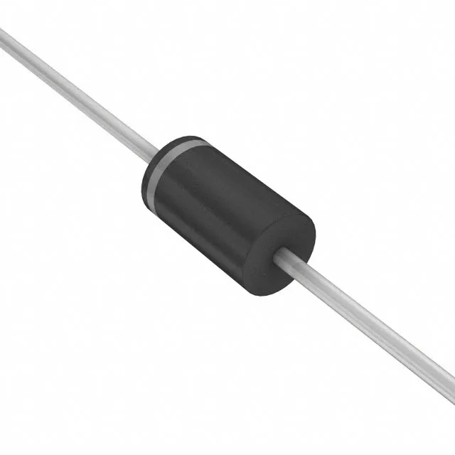
Supplied in a DO-201AA (DO-27) axial leaded package, through-hole mount. The DO-201 footprint is a standard 0.375-inch lead spacing — the same hole pattern used by 1.5KE, P6KE, and SA series TVS diodes, so a board already laid out for those families accepts this part without a layout change. Tape-and-box packaging (TB) per the evidence, not reel.
That spans the full industrial range and reaches into automotive underhood zones — an ECU on a 105°C ambient summer day still has 45°C of junction margin before derating. No power line protection (the device is not designed for AC mains clamping), so keep it on DC rails and signal lines.