1500W transient clamp for 459V rails
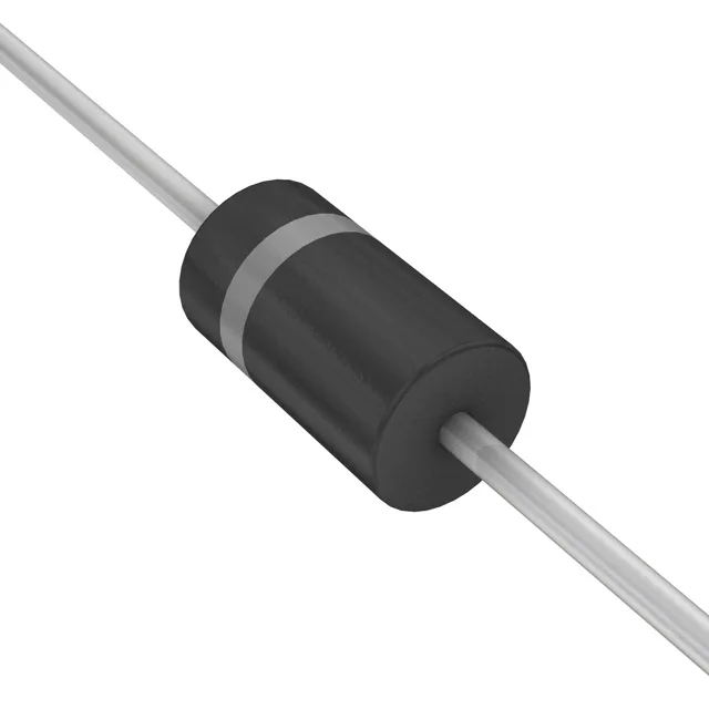
The 1.5KE540A/B: With a 459 V reverse standoff voltage and a 740 V clamping point at 2 A peak pulse current, it sits on a 400 V DC bus or a 277 V AC line and shunts transients that exceed the rail's dielectric withstand. The 513 V minimum breakdown voltage ensures the device stays off the rail during normal operation — the TVS only conducts when the transient pushes the line above that threshold. Unidirectional polarity means the cathode band marks the grounded side; reverse the orientation and the diode forward-conducts on the negative half-cycle.
DO-201 axial — board integration and thermal path
Housed in a DO-201AA (DO-27) axial leaded package, the 1.5KE540A/B mounts through-hole. The lead frame carries the transient current into the board copper; for a 1500 W pulse, the PCB pad area and trace width to the protected rail must handle the 2 A peak without fusing. The junction operates from -55°C to 150°C, so the part survives the thermal cycle of an outdoor enclosure or an engine bay without derating the standoff voltage. The axial body is box-packaged — the leads are formed for automatic insertion, and the part's 1500 W rating is tested with the device mounted on a standard copper-land pattern per the JEDEC 51-5 thermal reference. No power line protection (the flag) means this TVS is designed for signal, data, and DC bus clamping, not for mains AC surge suppression where a MOV or GDT would be the correct choice.