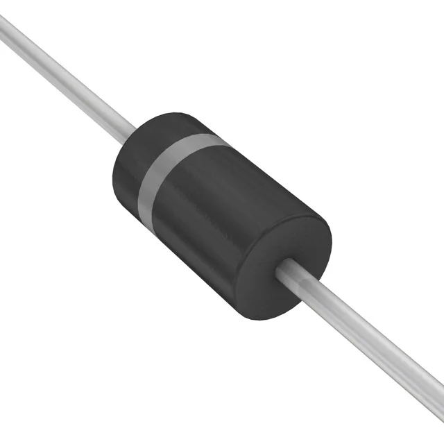
The 1.5KE16A/B: Its 13.6V reverse standoff voltage means it sits across a 12V nominal rail without conducting leakage current, then triggers at a minimum breakdown of 15.2V to clamp transients to 22.5V maximum.
Peak pulse current and clamping voltage — the survival numbers
At the 10/1000µs test waveform, the 1.5KE16A/B handles 67.6A peak pulse current before the clamping voltage reaches 22.5V. That 22.5V ceiling is the voltage the downstream circuit sees during the surge — a 12V-rated IC with 25V abs-max survives this, but a 5V logic rail would need a secondary clamp. The -55°C to 150°C junction temperature range covers both cold-start automotive and hot industrial enclosures. Derating the peak pulse power above 25°C follows the standard TVS derating curve — at 125°C ambient the effective power handling drops to roughly 75% of the 1500W rating.
DO-201 axial package and board integration
The DO-201AA (DO-27) axial-lead package is the standard through-hole TVS footprint. The 0.042-inch (1.07mm) lead diameter fits standard 0.040-inch PCB holes; the body length is about 0.375 inches (9.5mm). Bend the leads at a right angle for vertical mounting or leave straight for horizontal lay-flat on the board. The single unidirectional channel protects one signal line or one DC rail. For bidirectional or AC-line clamping, use the 'B' suffix variant of the same 1.5KE series — the 1.5KE16A/B order code as listed covers both unidirectional (A) and bidirectional (B) options in one part number.
No minimum order threshold beyond the standard reel or bulk pack quantity.