What the 15 A per diode rating means for your rail
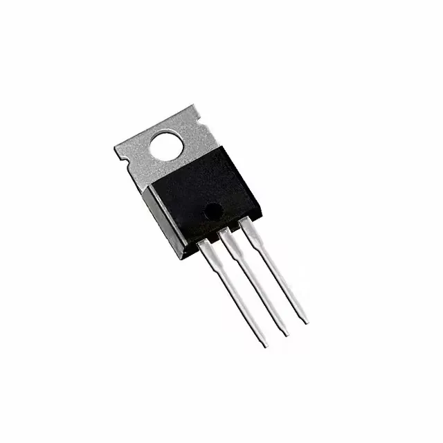
The V30120CI-M3/P: Each of the two common-cathode diodes is rated 15 A average rectified current (Io). In a center-tap full-wave configuration the pair shares the load, so the total DC output can reach 30 A before the junction hits thermal limits — but the TO-220AB package's thermal resistance to ambient is the real constraint. At 15 A per die the forward drop is 900 mV typ, so conduction loss per diode is 13.5 W; that needs a heatsink with a thermal path below about 3 °C/W to keep Tj under 150 °C in a 50 °C ambient.
120 V Vr and the leakage trade-off
Reverse voltage rating is 120 V maximum. At that voltage reverse leakage is 500 µA — typical for a trench Schottky of this die size. That leakage doubles roughly every 10 °C rise above 25 °C, so at 125 °C junction the leakage approaches 32 mA per diode and adds ~4 W of standby loss. For a power supply that spends most of its life in light-load or standby, the leakage at high temperature can dominate the no-load input power budget.
Common-cathode layout — one heatsink, two diodes
The 1 Pair Common Cathode configuration shares the center tab (pin 2) as the common output. That means a single TO-220AB tab electrically connects both cathodes — heatsink isolation is mandatory unless the heatsink itself is the output rail. The anode pins (1 and 3) are the individual inputs. This package mates into a standard TO-220 footprint; the 2.54 mm pin pitch and 0.9 mm pin diameter match any through-hole PCB layout for a 30 A bus.
RoHS3 — no exemptions to track
ROHS3 Compliant means all six restricted substances are below the threshold — no phthalate or lead exemptions that would expire or require a PCN.