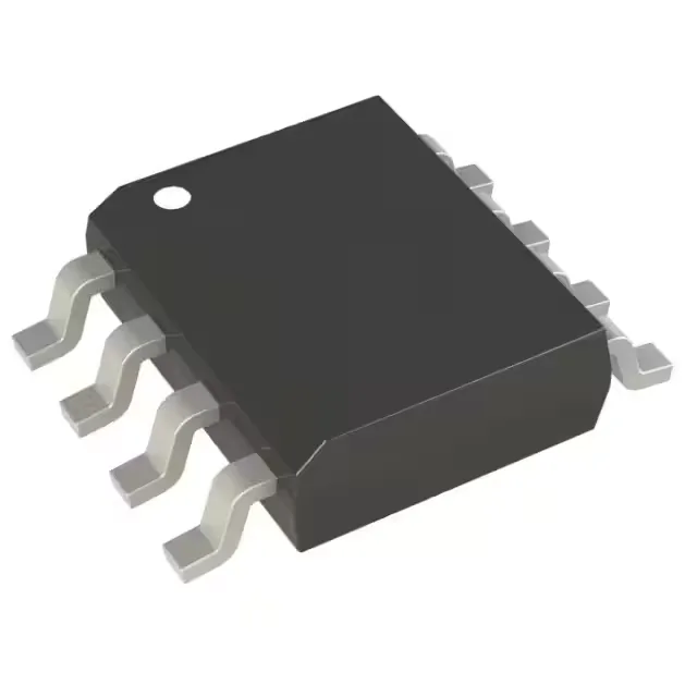
Vishay SQ4080EY-T1_BE3 — Discrete Semiconductors

Vishay SQ4080EY-T1_BE3 N-Channel MOSFET, 150V, 18A, 8-SOIC

MPNSQ4080EY-T1_BE3
End of Life

Vishay SQ4080EY-T1_BE3 N-Channel MOSFET, 150 V Vdss, 18 A continuous drain, 85 mOhm Rds(on) at 10 V, 33 nC gate charge, 8-SOIC package.

$1.35Ref. price · indicative, final on quote
Packaging8-SOIC (0.154", 3.90mm Width)
Independent supplier — new & surplus stockAuthenticity-screened · ESD-safe packingListing updated Aug 2026

Specifications

SQ4080EY-T1_BE3 specifications
ParameterValue
FET typeN-Channel
MountingSurface Mount
Drain to source voltage150 V
Drive voltage (Max rds on, min rds on)10V
Current - continuous drain (Id) @ 25°C18A (Tc)
Power dissipation7.1W (Tc)
Operating temperature-55°C ~ 175°C (TJ)
PackageTape & Reel (TR); Cut Tape (CT)
Vgs±20V
TechnologyMOSFET (Metal Oxide)
Case8-SOIC (0.154\", 3.90mm Width)
Vgs(th) (Max) @ id4V @ 250µA
Rds on (Max) @ id, vgs85mOhm @ 10A, 10V
Gate charge (Qg) (Max) @ vgs33 nC @ 10 V
Input capacitance (Ciss) (Max) @ vds1590 pF @ 75 V

Product details

The SQ4080EY-T1_BE3: That 150 V Vdss puts it solidly in the 48 V telecom bus, 72 V battery string, and 100 V intermediate-bus territory — plenty of headroom above a 48 V rail that can ring past 70 V during a hot-swap event. Maximum on-resistance is 85 mOhm at 10 A gate drive of 10 V, which is the stated drive voltage for achieving the rated Rds(on). At 18 A the conduction loss is I²R = 27.5 W — well above the 7.1 W package limit at Tc, so in practice the continuous current is thermally limited to about 9 A in free air on a standard 1 oz copper pad. The 85 mOhm figure is the one to use for loss budgeting at the nominal operating point, not the 18 A headline.

Gate drive and switching — the numbers behind the 33 nC Qg

Gate charge is 33 nC at Vgs = 10 V, and input capacitance (Ciss) is 1590 pF at Vds = 75 V. The gate-driver must source at least 33 nC per switching cycle; for a 100 kHz switching frequency that translates to 3.3 mA average gate current, well within a standard driver's capability. The 1590 pF Ciss means the gate rise time at a 10-ohm drive impedance is about 16 ns — fast enough for most hard-switching topologies, but the Miller plateau charge (Qgd, not listed here) is the real limiter for switching loss, so budget margin in the dead-time setting.

Active production — sourcing posture for this Vishay part

Lifecycle status is Active per the manufacturer (Vishay).

Frequently asked questions

How does SQ4080EY-T1_BE3 compare to SUD25N15-52-BE3?

The SUD25N15-52-BE3 is a higher-current sibling in the same TrenchFET family: 25 A continuous drain vs 18 A, with a lower Rds(on) of 52 mOhm at 5 A, 10 V. Both are N-channel, 150 V Vdss, 8-SOIC packages, and share the same ±20 Vgs max and 4 V threshold. The SUD25N15-52-BE3 has a slightly higher gate charge (40 nC vs 33 nC) and lower power dissipation (3.0 W vs 7.1 W). The SQ4080EY-T1_BE3 is the better fit when the BOM calls for 18 A max and the lower gate charge reduces driver loss.

Where can I buy SQ4080EY-T1_BE3 and what is the lead time?

Submit an RFQ for the quantity needed.