Active production — no last-time-buy scramble
Vishay lists the SIC651ACD-T1-GE3 as Active — no EOL notice, no NRND flag. For a BOM planner this means the part is still in the factory's standard ordering window; no need to hoard a last-time-buy or qualify a drop-in replacement yet.
50 A continuous, 100 A peak — the VRM stage budget
Rated 50 A continuous output per channel with a 100 A peak capability. That peak number is the pulse-handling limit for transient loads — a CPU core stepping from idle to full turbo draws that surge for tens of microseconds, and the DrMOS must deliver it without the inductor saturating or the output voltage collapsing below the load-line spec. The 24 V load rail and 4.5-5.5 V supply voltage tell you the gate-drive architecture: the high-side FET is bootstrapped off the 5 V supply, so the bootstrap capacitor must be sized for the PWM duty cycle and switching frequency. Diode emulation (included in the feature set) lets the low-side FET turn off during light-load periods, reducing reverse-recovery losses and improving efficiency below 10 A or so.
Fault protection set — what each guard catches
Over-current, over-temperature, shoot-through, and UVLO protection are integrated. Shoot-through prevention is the critical one for a half-bridge: it inserts a dead-time between high-side turn-off and low-side turn-on so the supply never sees a cross-conduction short. UVLO holds the outputs off until the 5 V supply is above the under-voltage threshold, which prevents the FETs from operating in the linear region during power-up.
PowerPAK MLP55-31L — layout and thermal notes
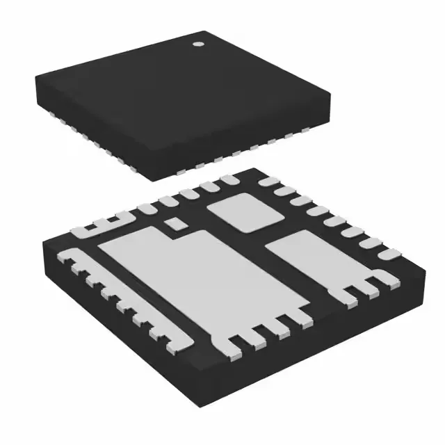
31-lead MLP55 package, 5 mm × 5 mm footprint. The exposed thermal pad on the bottom is the main heat path — the PCB must have a matching copper land and via array to the inner ground plane. Without that, the 150 °C junction rating is academic; the die reaches thermal shutdown well before the load current hits 50 A.
Available through independent distribution. No stock-holding claim — sourced per order.