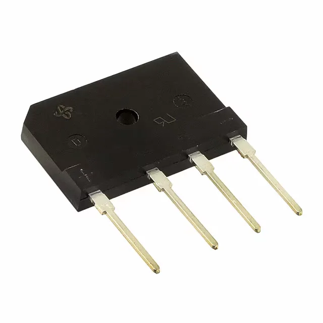
600 V, 45 A — sizing the front-end bridge
The PB5006-E3/45: The PB5006-/45 is a Vishay single-phase bridge rectifier in the isoCink+™ series, rated 600 V peak reverse voltage and 45 A average rectified output. These two numbers size the bridge for the bulk DC bus in a power supply front-end: 600 V PRV covers 240 VAC mains with margin for line transients, and 45 A Io supports a 2–3 kW output stage depending on topology and heatsinking.
Junction temperature range and thermal design
For a component engineer screening parts for an avionics PSU or a downhole instrument, this range means the bridge does not require a separate derating curve at the cold end and has headroom at the hot end before the silicon limits. The forward drop is 1.1 V typical at 22.5 A, which sets the conduction loss at roughly 25 W at half-rated current; the thermal path through the isoCINK+™ SIP package to the heatsink must keep Tj below 150°C at full load.
Package and isolation — isoCINK+™ SIP
The 4-SIP PB package (Supplier Device Package isoCINK+™ PB) is a through-hole, single-in-line footprint with transfer-molded isolation. The isoCINK+™ name refers to Vishay's molded SIP construction that encapsulates the die and bond wires in a single transfer-molded body — no separate potting or conformal coat needed for basic insulation. The tube packaging (50 per tube typical for this series) suits hand-insertion or wave-solder assembly; the SIP leads are on 0.100-inch pitch and mate with standard 0.025-inch square pin headers or solder into plated through-holes on a 1.6 mm board.
Reverse leakage and standby power
Reverse leakage is specified at 10 µA maximum at the full 600 V reverse voltage. At 25°C this is negligible — 6 mW dissipation in the blocking state. But leakage doubles roughly every 10°C junction rise; at 125°C the leakage can approach 1–2 mA, adding several watts of standby loss. A test engineer validating a low-standby-power design should measure leakage at the hot-end operating temperature, not just at 25°C, to confirm the budget.