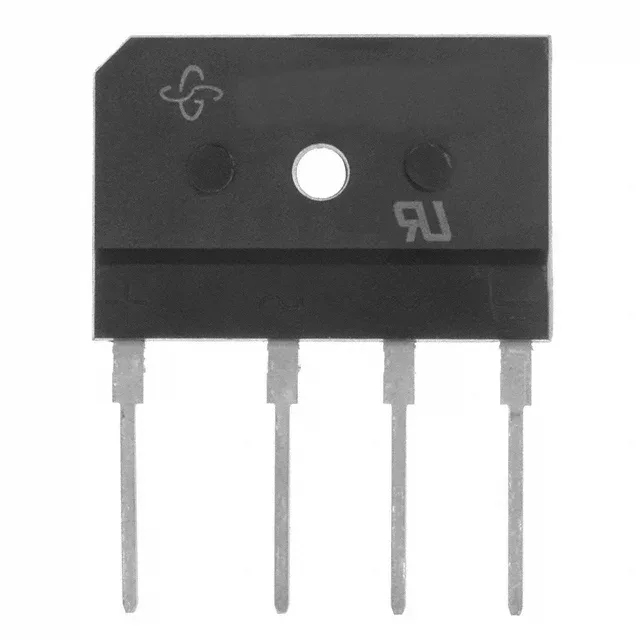
600 V peak reverse, 3.5 A average — the ratings that decide the bulk-capacitor bank
The GSIB1560-E3/45: The Vishay GSIB1560-/45 is a single-phase bridge rectifier in the standard GSIB-5S through-hole package. It delivers 3.5 A average rectified current (Io) and blocks 600 V peak reverse voltage — the two numbers that size the input diode bridge for a bulk-capacitor front end in a line-frequency supply. Forward voltage drop is specified at 950 mV typical when the device is conducting 7.5 A — this is the conduction loss figure for thermal design, not the rated average current. The 3.5 A Io rating is the continuous DC output the part can sustain; the 7.5 A condition in the Vf spec is a pulsed or surge-level test point.
Package and thermal environment
The GSIB-5S is a 4-pin single-in-line through-hole package with a 5.08 mm pitch. The 150 °C upper limit is the absolute maximum; the datasheet derating curve (page 3) shows the output current must be reduced above 100 °C ambient. For a 60 Hz line input the rectifier sees a 120 Hz ripple current — the RMS value, not the DC average, heats the junction.
Reverse leakage and blocking behaviour
Reverse leakage current is 10 µA maximum at the rated 600 V reverse voltage and 25 °C junction. Leakage doubles approximately every 10 °C rise — at 125 °C it is in the hundreds of microamps range, which matters for the bleeder resistor sizing in a capacitive dropper or for the hold-up time calculation in a discharge circuit.