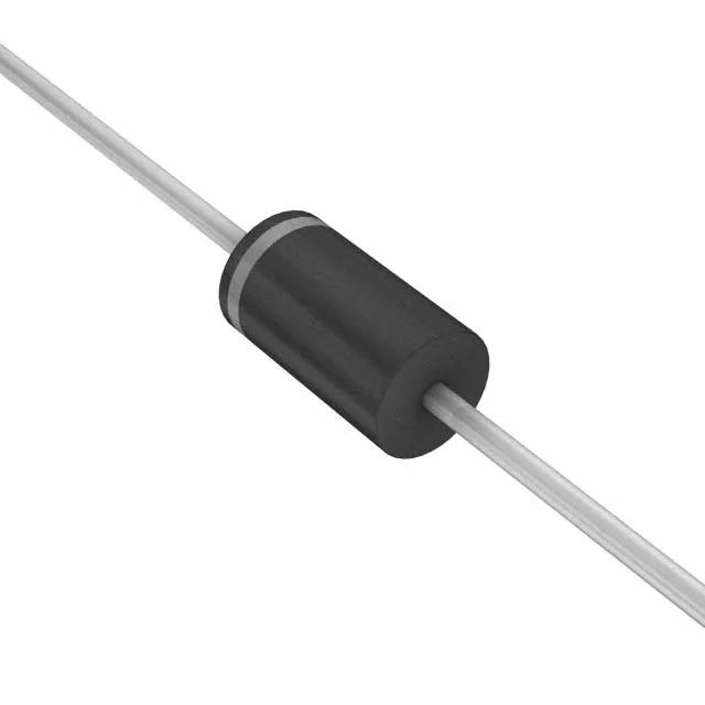
1.5 kW transient suppressor in the automotive stack
The 1N6280AHE3_A/D is a unidirectional Zener-based transient voltage suppressor (TVS), packaged in the DO-201AA axial outline and qualified to AEC-Q101 for automotive environments. The TransZorb® series designation means the clamping element is the Zener junction itself — it absorbs the surge energy and clamps the overvoltage in one shot, rather than crow-barring into a hard short. This makes it a common choice on power rails ahead of sensitive ICs in engine-control units, instrument clusters, and other 12 V automotive boards where load-dump transients are a known hazard.
What the clamping specs mean for the protection window
The reverse standoff voltage of 20.5 V sets the normal working rail — the TVS stays off and draws only leakage current while the bus sits below this threshold. In a 14 V automotive system, a load-dump spike that drives the rail above 22.8 V triggers the clamp and holds the downstream circuitry at or below 33.2 V — that 10 V headroom between standoff and clamp is the design margin the protection engineer sizes the catch diode against. This is the ISO 7637-2 pulse 5 (load dump) test shape, so the rating maps directly to the automotive transient immunity test the ECU must survive. Switching the waveform to a faster 8/20 µs surge reduces the allowable peak current — the energy in the pulse is lower, so the device can survive a higher peak amperes, but the voltage overshoot during the rise time becomes the concern.
Junction temperature and the automotive thermal envelope
In an engine bay module, board-level temperatures routinely reach 125°C ambient at the ECU housing — the Zener dissipating even a few hundred milliwatts of clamp energy will self-heat above that ambient, and the 175°C junction limit gives headroom for short transient spikes without the part entering thermal runaway. The DO-201AA axial leadframe also acts as the primary thermal path to the board pad, so the land pattern and solder joint quality directly affect the thermal resistance the datasheet specifies.
Tape & Box packaging — through-hole assembly note
Supplied in Tape & Box (TB) — a straight-lead axial format, not a gull-wing or BGA. The DO-201AA body sits on a 3.5 mm lead pitch, which is wider than most bypass caps and resistors on the same board and allows hand-solder or wave-solder mounting without tight coplanarity concerns. The through-hole mount also means the device can be supported by its leads on both sides of the board — useful in vibration-heavy underhood applications where a surface-mount body is at risk of cracking on thermal cycling.