What the 5 kW peak-pulse rating means for clamping selection
The 5KP22AHE3_A/C: At 141 A peak pulse current, it handles the current limb of that event without going into thermal runaway, provided the event is brief. The clamping ceiling of 35.5 V at peak current is the voltage the protected node sees when the surge is at its worst; the reverse standoff of 22 V sets the maximum working DC rail this part can sit across continuously without conducting.
The voltage envelope — standoff, breakdown, and clamping
24.4 V minimum breakdown and 22 V typical reverse standoff define the selection window: the part sits idle below 22 V, begins conducting above 24.4 V, and clamps the surge at 35.5 V. For a 24 V nominal bus that can ring to 35–40 V during a transient, this is the right clamping headroom — the TVS activates before the downstream semiconductor sees damaging overvoltage.
Automotive grade and thermal margin
AEC-Q101 qualification means the part passed the automotive discrete-stress battery: temperature cycling, humidity, peak pulse power, and steady-state operating life at the junction temperature limit. Telecom is listed as the application, but the AEC-Q101 thermal envelope makes it suitable for any automotive or industrial environment where the junction stays within that window.
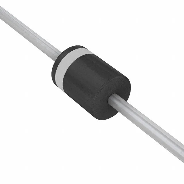
P600 axial leaded package — board integration note
Through-hole P600 package requires two lead holes on the PCB, typically on a 25.4 mm (1-inch) pitch for the larger P600 outline. The leads conduct heat away from the junction into the board copper, so a beefy anode pad and cathode pad with thermal via arrays under each lead help keep Tj down during a large transient. For Telecom boards the through-hole form factor is an advantage — the lead inductance is higher than a surface-mount TVS, which slightly softens the clamping edge, but the peak let-through voltage is still well within the 35.5 V ceiling.