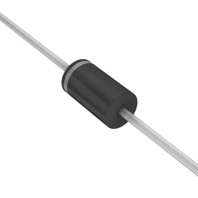
The 1N6278A-E3/54: The 1.5 kW peak pulse rating (10/1000 µs waveform) defines the device's ability to absorb a single high-energy transient — a lightning surge, inductive kick, or switching spike — without degrading. That 54.2 A peak pulse current at 27.7 V clamping voltage is the clamping ceiling under the standard IEC 61000-4-5 test wave. The actual let-through voltage seen by the protected load stays at or below 27.7 V as long as the event energy stays within the 1.5 kW rating window. Exceed it and the part goes into conduction collapse. The 17.1 V reverse standoff typ and 19 V minimum breakdown define the normal operating band — the TVS sits idle below 17.1 V and begins to avalanche above 19 V. For a 24 V nominal rail, the standoff margin is tight enough to need careful derating: a 10 % rail variation puts 26.4 V on the line, leaving barely 2.6 V before the breakdown threshold. Verify the worst-case rail sits comfortably below the standoff ceiling for reliable idle operation.
Junction temperature and deployment context
The -55°C to 175°C junction temperature range places this part in the high-reliability and industrial grade band. The upper limit is governed by the silicon junction, not the housing — the DO-201AA body dissipates heat through the leads into the PCB pad and surrounding copper. In a still-air enclosed panel, budget the thermal path from lead to ambient to confirm the junction stays below 175°C under continuous standby at the reverse standoff voltage. As a through-hole axial part in the DO-201AA package, this TVS is wave-soldered or hand-soldered during board assembly — not a hot-air reflow part. The 1.5KE device package designation in the supplier listing ties directly to the 1.5 kW peak pulse power class, which is the key sizing parameter when selecting a replacement across the 1.5KE family.