Transient suppression ratings — what the numbers decide
The 1N6277A-E3/54: The 15.3 V typical reverse standoff is the working voltage at which the TVS sits idle in normal operation; the 17.1 V minimum breakdown is where it begins conducting. A unidirectional TVS of this class is the right fit across secondary-side protection on power rails, input clamps on industrial I/O, and transient absorption on telecom bus nodes — anywhere a fast-clamp response below a few hundred nanoseconds is required and the 1.5 kW peak budget covers the threat magnitude.
Peak pulse power and surge budget
The 59.5 A peak pulse current tells you the surge current the part survives during a single event; the clamping voltage at that current is what the downstream circuit actually sees. A 1.5 kW/59 A TVS in the 15–25 V working range covers 24 V industrial rails and 12 V automotive nodes where the surge threat is IEC 61000-4-5 Level 4 or below.
Temperature grade and junction environment
The -55 °C to 175 °C junction temperature range signals the part is qualified for the extended thermal environment of industrial enclosures, engine-adjacent modules, or any design where transient self-heating during a surge event can push the junction above the typical 125 °C ceiling. Junction temperature is the limit; the thermal resistance from junction to lead determines how quickly the part self-heats during a 10/1000 µs pulse — design the lead length and pad thermal relief accordingly to stay below 175 °C at the worst-case surge repetition rate.
Package, mounting, and sourcing posture
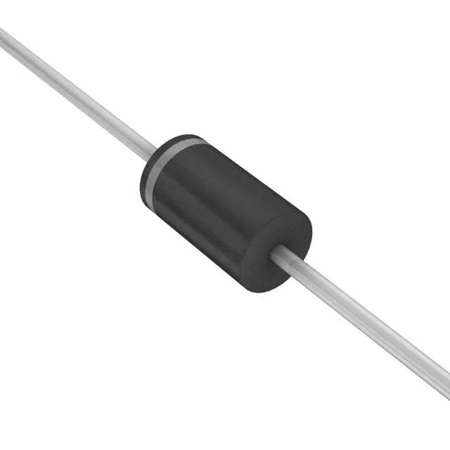
The DO-201AA axial body is the through-hole form factor most buyers associate with the legacy 1N TVS family — it mounts in a standard 0.4-inch lead spacing footprint on a PCB or pigtail-connects into a harness entry point. Taped-and-reeled packaging supports automated insertion; cut-tape is available for prototype quantities. The base product number 1N6277 groups this part into the broader 1.5KE family so alternative voltage selections within the series are pin-compatible drops.