What the voltage window means for protection
The 1N6273AHE3_A/D: The reverse standoff of 10.2 V typ defines the working voltage — the protected rail runs at or below this level under normal conditions, with the diode presenting a high impedance. The minimum breakdown voltage is 11.4 V at 1 mA test current, which marks the onset of conduction — the protection window spans from 10.2 V reverse standoff to the 16.7 V clamping ceiling, and that 5.5 V overhead is what downstream ICs and connectors see during a surge. Maximum clamping voltage of 16.7 V at the 10/1000 µs peak pulse current of 89.8 A sets the let-through ceiling — this is the stress the protected load actually survives, and 89.8 A of survivable fault current confirms the device does not go short-circuit under surge.
Temperature grade and package for automotive deployment
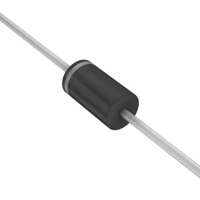
The DO-201AA axial package with through-hole mounting is the standard footprint for board-level DC-rail surge protection — wave-solder compatible, and the 1.5KE supplier package code confirms the mechanical outline matches the industry-standard outline used across multiple manufacturers. Tape-and-box packaging is the through-hole insertion format for EMS lines running auto-placement — verify pitch spacing on the insertion tooling before committing a high-run BOM.
Listed Active by Vishay General Semiconductor — quoted to order through independent distribution with full traceability; lead time and pricing confirmed at RFQ. The 1.5KE package code is the industry-standard outline shared across multiple TVS manufacturers — a same-footprint cross-reference from an alternate Vishay division or second-source line is worth checking in the cross-reference table before committing to a single source.