The 1N6269A-E3/54: A 124A peak pulse current at that same wave shape is what flows through the device during the clamping event; the 12.1V maximum clamping voltage is what the downstream circuit sees while that current is diverted. The gap between the 7.02V reverse standoff and the 12.1V clamping ceiling is the protection window — the standoff keeps the protected rail quiet under normal operating voltage, and the clamping ceiling caps the overvoltage during the transient. Choosing the right standoff means picking a rating safely above the circuit's normal working voltage but below any voltage the protected load cannot tolerate.
Thermal margin — the temperature spec that gates the surge derating curve
Rated junction temperature runs from -55°C to 175°C — the wide lower bound handles cold-start and outdoor deployments without derating, and the 175°C ceiling gives headroom above the clamping thermal spike. The 1.5kW rating is a function of the transient energy the junction can absorb without exceeding that temperature limit; sustained or repetitive pulses above the rated duty cycle push the thermal budget toward the ceiling, so the datasheet derating curve — not just the headline number — is the document to pull before committing to a repetitive-surge application like motor or transformer inrush.
TransZorb versus a plain Zener — what the series designation changes
The TransZorb designation marks this as Vishay's voltage-clamping transient suppressor variant, not a conventional Zener used for voltage reference. It is specified for peak pulse handling and clamping performance, whereas a standard Zener datasheet would centre on the Vz reference voltage and its tolerance band. The 7.79V minimum breakdown and 12.1V clamping voltage are the figures a protection-network designer works from; the Vz tolerance band that matters for a reference circuit does not appear in this listing. As a single unidirectional channel, the device clamps positive-going transients on one polarity only — it does not provide bipolar protection without a second device reversed in parallel.
DO-201AA axial package — panel and harness integration
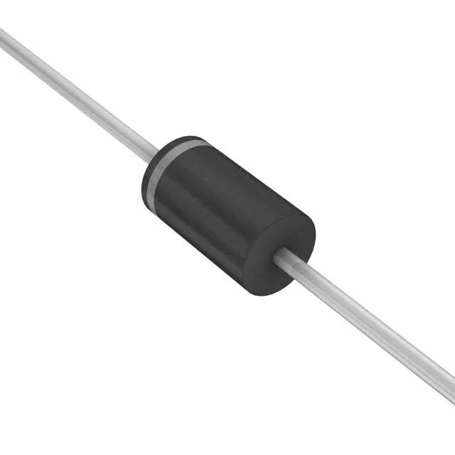
The DO-201AA (also styled DO-27) axial through-hole package mounts in a board hole or a panel-mounted clip and solders directly to PCB pads or a wiring terminal. The through-hole leadform provides mechanical retention that surface-mount devices lack — a meaningful advantage in applications where vibration or thermal cycling can loosen a solder joint. Tape-and-reel and cut-tape packaging options serve automated insertion and manual kitting respectively.