Transient suppression — what the voltage window means
The 1.5SMC82A-E3/9AT: The 1.5SMC82A-/9AT is a unidirectional TVS diode from the 1.5SMC series, Vishay's TransZorb® family. It clamps voltage transients across a three-point window: 70.1 V typical reverse standoff (VRWM — the maximum working voltage it blocks without conducting), a 77.9 V minimum breakdown voltage (where it begins to avalanche), and a 113 V maximum clamping voltage at the rated peak pulse current. The 70.1 V standoff places this squarely in the protection zone for 24 V industrial buses — transients on that rail will be steered into the clamp before they reach the 113 V ceiling on any downstream load. Peak pulse power is 1500 W (1.5 kW) at the standard 10/1000 µs waveform — a fast-rise, slow-decay surge representative of inductive load kick and lightning-coupled transients on distribution circuits. At that same waveform the peak pulse current reaches 13.3 A. These two figures together define the energy class the board designer uses to select the diode for a given bus exposure zone, not the steady-state current rating.
DO-214AB SMC — board footprint and thermal relief
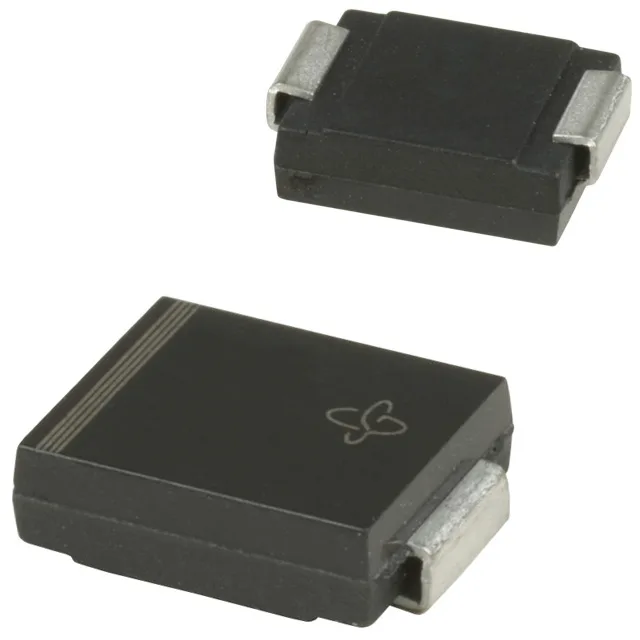
The supplier device package is DO-214AB (SMCJ) — the SMC variant of the standard DO-214AB outline. The cathode pad soldered to the protected rail carries the surge current to the chip; the anode returns to the local ground plane. For a 1.5 kW clamp the copper pad area under the package termination directly affects the thermal path from junction to board, so board-level thermal relief matters more than package style. The part tolerates a junction temperature up to 150 °C across a storage range of -65 °C to 150 °C, giving headroom in enclosed panels without active cooling. Supplied in Tape & Reel (TR) — the orientation for high-volume SMT line placement. There is no power-line protection flag on this specific variant, so for primary power-bus clamping on the mains side a higher-rated part from the same series or a dedicated power-SCR crowbar device would be the front-end complement, with the 1.5SMC82A as the secondary clamp protecting downstream active circuits.
Listed as Active by Vishay General Semiconductor — Diodes Division. No NRND notice, EOL date, or official successor order code appears in the ledger for this specific variant. Sourced and quoted to order; availability and current pricing confirmed at RFQ time through independent distribution.