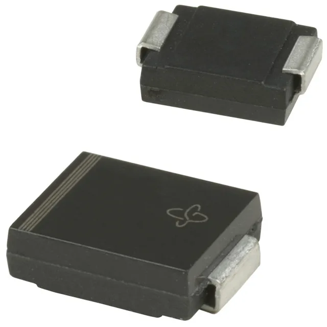
Clamping voltage and the 124 A surge ceiling
The 1.5SMC8.2AHM3_A/H: The 12.1 V clamping voltage at Ipp=124 A defines what the downstream circuit must survive — the downstream rail protection staging needs to hold below the INPUT clamp level of whatever is behind it. The 7.02 V reverse standoff is the working voltage in normal operation; the 7.79 V minimum breakdown is where the device begins conducting in the reverse direction.
Using this diode against a faster 8/20 µs surge (often seen in automotive load-dump profiles) requires checking the peak current and energy capability separately; the datasheet peak pulse current of 124 A at 10/1000 µs is the governing number for that waveform, and the energy let-through at 8/20 µs will be lower because the pulse width is shorter.
AEC-Q101 qualification and the automotive deployment envelope
The AEC-Q101 qualification means this part has passed the automotive stress tests for discrete semiconductors — including high-temperature reverse bias (HTRB), temperature cycling, and humidity testing. The Tj rating of -65°C to 150°C puts it in the upper tier for under-hood applications; the base plate rating, not the ambient, sets the junction temperature limit, so the thermal path from the DO-214AB solder joint to the PCB copper under the cathode tab determines the actual operating margin.