What the voltage ratings mean on the bench
The 1.5SMC75CA-E3/57T: The standoff of 64.1 V keeps the diode off during normal rail operation — only transients that push the node above roughly 71.3 V (breakdown) and up to 104 V (clamp) see conduction, which means the clamping window is narrow enough to protect downstream silicon without letting through prolonged overvoltage. At a 14.6 A surge current the clamp sits at 104 V, which means the protected node sees a maximum of 104 V regardless of how high the incoming transient tries to push it — the downstream IC sees that ceiling, not the raw surge amplitude.
Package and what it asks of the board
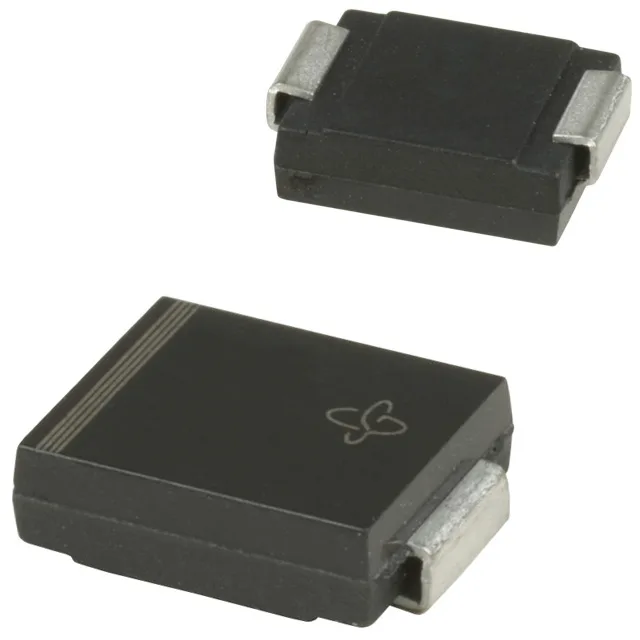
The DO-214AB (SMC) is a standard surface-mount outline — the cathode tab is the primary thermal path, so the pad footprint and solder joint geometry directly set the junction-to-ambient thermal resistance; thermal relief on the pad matters more than the part itself for long-term reliability under repeated transients. Reel packaging signals the part is reeled for high-speed pick-and-place — confirm the reel pitch and leader length match the mounter's feeder specification before committing to the panel layout.
Where the temperature and qualification grade put this part
Power line protection is listed as No — this part is not UL 497B listed for dedicated telecom loop circuits; it serves as a general board-level transient suppressor on data, control, or power rails that do not require that certification.
Active status and sourcing posture
The standard SMC footprint means pin-compatible cross-parts exist across the TVS diode market if a second-source hedge is needed for the BOM position.