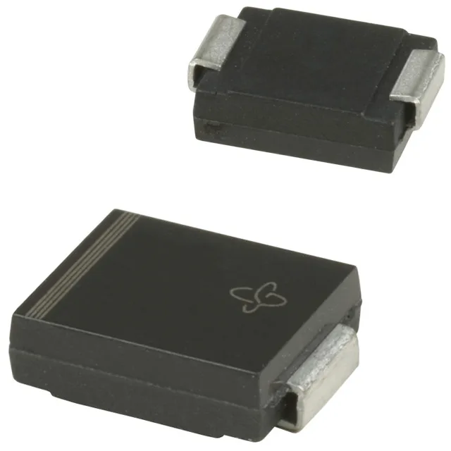
The 1.5SMC75AHM3_A/H: That 104 V clamping ceiling is the stress voltage the protected downstream circuit sees — sizing the TVS around the clamping voltage, not the standoff, is what keeps the downstream bus within its absolute-maximum rating during the transient event.
Reverse standoff and breakdown — the protection window
The reverse standoff voltage sits at a typical 64.1 V, meaning the TVS stays invisible to the normal bus — it does not conduct until the transient pushes the line above 71.3 V minimum breakdown. The gap between 64.1 V standoff and 71.3 V breakdown is the design headroom; the rail being protected should sit cleanly inside that window so the TVS never leaks appreciably in normal operation. The 150 °C ceiling gives thermal headroom above most automotive under-hood conditions, but the clamping energy and mounting thermal resistance still govern the actual Tj rise in a closed enclosure.
AEC-Q101 qualification and automotive fit
The series designation Automotive, AEC-Q101, 1.5SMC, TransZorb® places this part in the automotive-screened grade — the qualification covers temperature cycling, humidity, and surge testing to the AEC-Q101 stress levels. For an automotive ECU input or telecom rail feeding sensitive circuitry, the AEC-Q101 badge is the signal that the lot traceability and production part approval process meet the automotive OEM standard, not just the commercial screening pass/fail.
Package and sourcing posture
The DO-214AB (SMC) package is the standard JEDEC footprint for the 1.5SMC series — surface-mount reflow, tape-and-reel packing. The part carries the base product number 1.5SMC75, which is the identifier to use when cross-checking against alternate distributors or checking second-source availability within the same Vishay series footprint.