Clamping, standoff, and breakdown — what the three voltages mean for the protection window
The 1.5SMC75AHE3/9AT: The 64.1 V reverse standoff rating is the voltage the TVS sees in normal operation — the circuit runs below this without the device conducting. The 71.3 V minimum breakdown is where the TVS begins to clamp; above this threshold the Zener avalanche kicks in and the device presents a low-impedance path to ground. The 104 V maximum clamping voltage is what the downstream sensitive circuitry sees at the rated peak pulse current of 14.6 A — that 104 V ceiling is the design limit the protected side must withstand.
Sizing against a fast-clamp TVS table while the threat is a 10/1000 µs load dump produces a conservative result, which is appropriate for automotive. The 14.6 A peak pulse current at the clamping voltage confirms the device handles the current through the TVS at the moment the clamp is active.
AEC-Q101 qualification and the automotive deployment envelope
The AEC-Q101 qualifier on this series confirms the part has passed the automotive stress-sequence — temperature cycling, high-temperature reverse bias, and terminal strength — at the component level before entering a module-level qualification flow. Junction temperature is rated to 150°C, and the -65°C lower limit covers cold-start conditions. The TransZorb® designation is Vishay's voltage-clamping geometry, meaning the response is bidirectional Zener-style avalanche, not a thyristor crowbar — the clamping voltage rises with current rather than latching, which keeps the protected circuit in a defined overvoltage state until the transient passes.
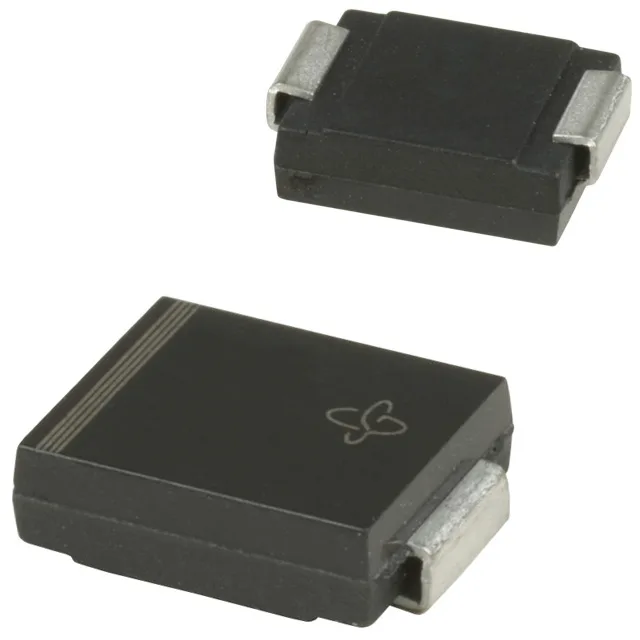
DO-214AB footprint and surface-mount assembly
The Tape & Reel packaging is the standard carrier format for automated placement; confirm the reel diameter and tape width against the assembly line feeder specification. Surface-mount TVS in this package class does not require a heatsink — the PCB pad area and the board copper define the thermal resistance from junction to ambient.