Transient clamping — what the ratings mean in-circuit
The 1.5SMC7.5A-E3/9AT: The 11.3V maximum clamping voltage at 133A peak pulse (10/1000µs waveform) is the number that determines let-through voltage on the protected rail — the TVS absorbs the surge and clamps the downstream IC at or below that level. With a 6.4V reverse standoff, the device sits passively on the rail at normal operating voltage; it does not conduct until the transient pushes the line above the 7.13V minimum breakdown threshold. The 1500W peak pulse rating defines the surge energy the part can absorb in the specified 10/1000µs event — this is the primary selection parameter for boards exposed to lightning transients or inductive kickback on supply lines.
Package, temperature, and design-in fit
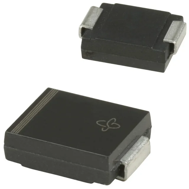
The DO-214AB (SMC) package is the standard JEDEC SMC outline — the cathode bar on the housing identifies polarity, and the layout follows the typical two-pad SMD footprint with a recommended land pattern for optimal thermal relief under the cathode tab. Junction temperature rating of -65°C to 150°C covers the full industrial envelope — a 105°C ambient with self-heating from the clamping event still leaves margin before the 150°C Tj ceiling. Single unidirectional channel means this part protects a positive-going supply rail — it does not clamp negative transients; a dual-directional TVS or opposite-polarity diode handles the negative side if required.