The 1.5SMC68CAHM3_A/I: That is the primary selection axis for any overvoltage protection slot, and this rating positions the part for the higher-energy transients seen on supply rails and signal lines in both automotive and telecom equipment, not just low-energy signal clamping. The standoff voltage is 58.1 V typical reverse standoff — the working voltage the TVS sees in normal operation without conducting. The breakdown minimum of 64.6 V sets the threshold where the device begins to clamp, and the clamping ceiling is 92 V maximum at the 16.3 A peak pulse current, which is the voltage appearing at the protected node when the full surge current is flowing. The bidirectional configuration with a single channel means the part clamps both polarities — relevant for data lines and rails that see both positive and negative transients relative to ground.
AEC-Q101 qualification for automotive and telecom deployment
Operating junction temperature runs to 150 °C, with a minimum rated down to -65 °C — the wide junction range covers both engine-bay ambient spikes and outdoor equipment in cold climates. The Tj rating is the junction, not the ambient, so the thermal resistance of the PCB pad and copper footprint determines how close the die runs to the ambient temperature in a given enclosure.
SMC (DO-214AB) package and surface-mount footprint
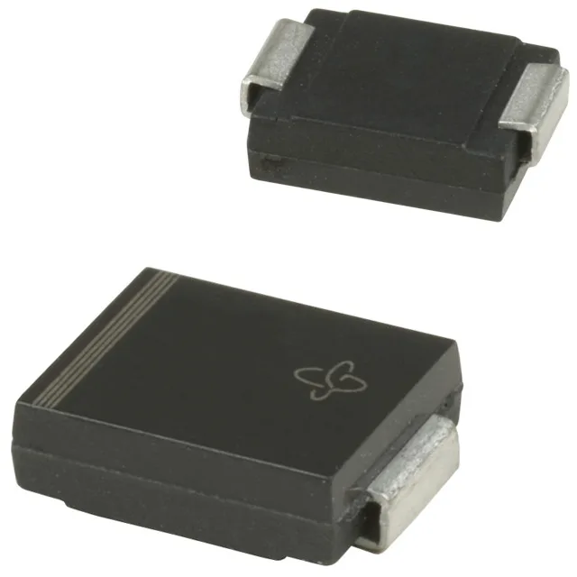
The DO-214AB (SMC) package is the standard surface-mount TVS footprint — the cathode band marks the cathode side and the full-width anode pad sits opposite. The wide metal tabs on both terminations carry heat away from the junction to the PCB copper, and the recommended land pattern uses a full-termination pad width to maximise the thermal path for repetitive surge events. Tape-and-reel packaging aligns with standard SMT assembly flow — the part is compatible with standard pick-and-place routines for SMC components. Confirm the reel quantity matches the assembly lot size; mixed-reel loading in high-volume automotive builds is a rework trigger.