What the 68V clamping triplet means for your rail
The 1.5SMC68CA-M3/9AT is a bidirectional Zener-based transient voltage suppressor — the TransZorb® series from Vishay General Semiconductor. Three voltages define its protection window: 58.1 V reverse standoff (the normal working rail the diode ignores), 64.6 V minimum breakdown (where it starts conducting), and 92 V maximum clamping voltage at the rated peak pulse current. For a nominal 48 V rail, the 58.1 V standoff gives about 10 V of headroom — enough to keep the TVS dormant during normal operation while clamping inductive kickback or surge events before they reach the load.
At that pulse shape the diode clamps at 92 V maximum while conducting up to 16.3 A peak. Sustained overvoltage above the standoff will push the device into avalanche — the 150 °C maximum junction temperature is the hard ceiling for thermal survival during a fault event, so the board-level thermal design must keep the case temperature below whatever derating the application environment demands.
DO-214AB SMC footprint and board considerations
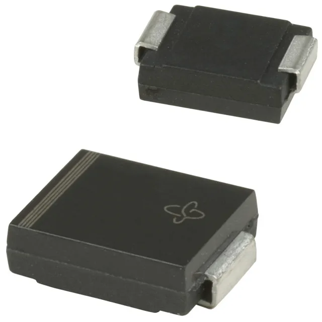
The SMC (DO-214AB) package is the mid-size SMC J-bend leadform — pin-compatible across most 1.5SMC, 5SMC, and SMB families from multiple manufacturers. The cathode band marking identifies the anode/cathode orientation on the unidirectional variant; this part is bidirectional so orientation is non-critical. The exposed pad on the bottom connects to the cathode electrically and provides the primary thermal path to the board copper — a appropriately sized landing pad and thermal via cluster directly under the pad are required to realise the 1500 W peak rating in practice.