What the clamping and standoff ratings mean for telecom protection
The 1.5SMC62AHM3_A/I: With 53V typical reverse standoff voltage and a 58.9V minimum breakdown, the device sits above the nominal rail it protects, drawing only leakage current in normal operation. When a transient arrives, the 85V maximum clamping voltage at 17.6A peak pulse (10/1000 µs) is the ceiling the downstream circuitry sees — the 1.5kW peak pulse rating tells you the part survives a single-event surge of that energy without degradation. For a telecom line card running 48V nominal, the 53V standoff gives ~10% headroom above the working rail while clamping events to 85V, well within the withstand rating of most PHY transceivers.
Automotive qualification and thermal envelope
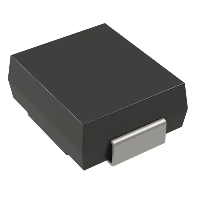
The AEC-Q101 qualification means the part has passed automotive-grade reliability stress testing — temperature cycling, humidity, surge life — the screening level telecom industrial applications often borrow from. The DO-214AB (SMC) package is the standard 2-pin SMA-size outline — the cathode band marks the unidirectional polarity. Surface-mount termination suits reflow assembly on multi-layer boards; the exposed pad under the body is the thermal path to the PCB copper. Tape-and-reel packaging aligns with automated pick-and-place. Confirm the reel direction and leader/trailer length against your feeder spec — the ordering code suffix _A/I encodes the automotive grade and reel orientation, which is the detail that trips up hand-assemblers who assume the unmounted variant.
The 1.5SMC62AHM3_A/I carries Active lifecycle status from Vishay General Semiconductor — Diodes Division. Confirm the exact suffix — automotive grade and reel orientation — against your house part number before committing.