Standoff voltage and the clamping ceiling
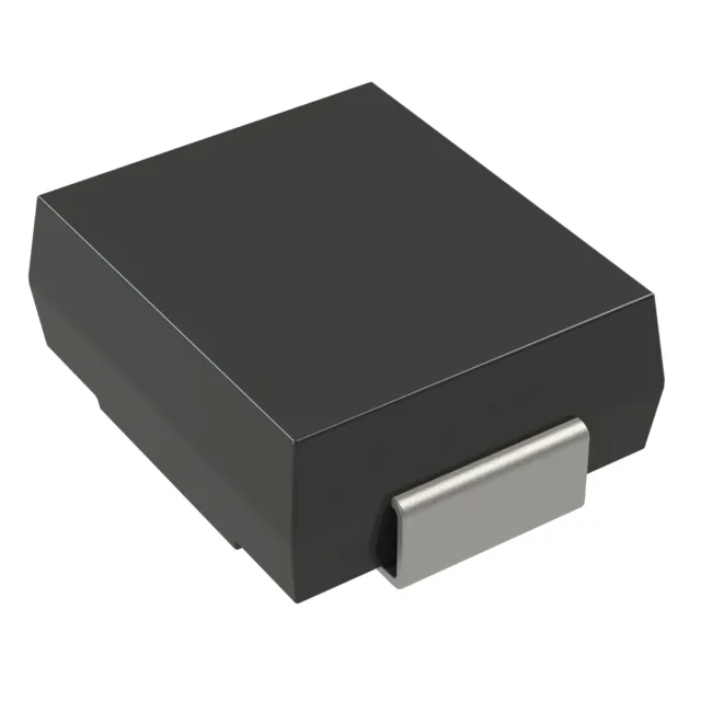
The 1.5SMC6.8CAHM3_A/I: The standoff voltage of 5.8 V sets the normal-operation ceiling — the TVS stays off and draws only leakage current up to this level, so it does not clamp the protected rail during start-up or transient-free operation. At 5.8 V nominal, the standoff sits roughly 12 % above a 5 V rail and 76 % above a 3.3 V rail — the two most common telecom logic rails. This gives the protected node adequate headroom against spurious conduction on either rail without requiring a lower-standoff part that would consume more clamping budget. The bidirectional polarity means the 5.8 V standoff and the 6.45–10.5 V clamping window apply to both polarities equally, with no need to separate the positive and negative protection rails in a differential telecom interface.
Peak pulse capability and surge handling
The 1.5 kW figure is the clamping-mode dissipation capacity, not a continuous rating — the transient thermal impedance curve in the Vishay datasheet determines the actual junction temperature rise per surge event. Peak pulse current of 143 A at the standard 10/1000 µs waveform validates the surge-handling ceiling for the listed 1.5 kW. The two figures must be read together: a TVS that clamps at 10.5 V and conducts 143 A delivers 1.5 kW into the clamping mode. Specifying one without the other leaves the surge budget undefined.
Automotive qualification for telecom deployment
AEC-Q101 is the automotive discrete semiconductor qualification standard covering temperature cycling, humidity, mechanical stress, and electrical testing. A part that passes AEC-Q101 is accepted for engine-compartment and chassis-domain deployment — the thermal and mechanical margin it carries is more than sufficient for the board-level operating environment in a telecom enclosure or outdoor cabinet. Operating junction temperature range is -65 °C to 150 °C, with the maximum rated junction temperature also at 150 °C. This gives the design a 0 °C margin at the upper bound — normal for a Tj(max) part — and the full span accommodates both cold outdoor telecom cabinet temperatures and any self-heating from repetitive clamping events. The listed telecom application reflects the part's original qualification target; the automotive grade extends that thermal and mechanical margin to any industrial or infrastructure installation where board-level protection with proven stress testing is required.