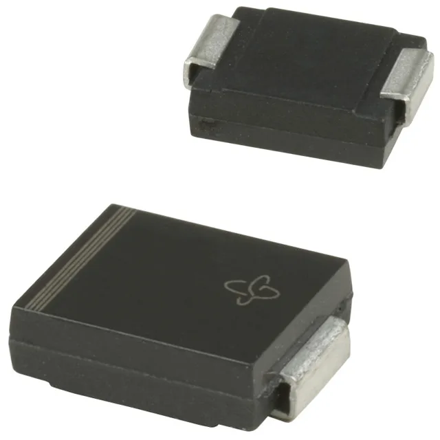
Vishay General Semiconductor - Diodes Division 1.5SMC6.8CA-E3/57T — Circuit Protection

Vishay 1.5SMC6.8CA-E3/57T TVS Zener, 5.8V Standoff, DO-214AB

MPN1.5SMC6.8CA-E3/57T
Active

Vishay General Semiconductor 1.5SMC6.8CA-/57T, 1.5SMC TransZorb® series, bidirectional TVS Zener, DO-214AB (SMC) surface-mount package, 5.8V reverse standoff, 10.5V clamping at 143A peak pulse, 1500W peak pulse power, -65°C to 150°C junction operating range, Tape & Reel and Cut Tape packaging.

Independent supplier — new & surplus stockAuthenticity-screened · ESD-safe packingListing updated Aug 2026

Specifications

1.5SMC6.8CA-E3/57T specifications
ParameterValue
TypeZener
Series1.5SMC, TransZorb®
MountingSurface Mount
Voltage - breakdown6.45V
Voltage - clamping (Max) @ ipp10.5V
Voltage - reverse standoff5.8V
Current - peak pulse (10/1000μs)143A
Power - peak pulse1500W (1.5kW)
Power line protectionNo
Operating temperature-65°C~150°C(TJ)
PackageTape & Reel (TR); Cut Tape (CT)
ApplicationsGeneral Purpose
CaseDO-214AB, SMC
Bidirectional channels1

Product details

What 1.5SMC6.8CA-E3/57T protects — and why the voltage ratings matter

The 1.5SMC6.8CA-/57T is a bidirectional TVS Zener (Vishay's TransZorb® series) in the DO-214AB SMC package — a transient voltage suppressor that clamps fault surges to a defined level before they damage the protected rail. The "CA" suffix denotes bidirectional polarity, meaning the part clamps both positive and negative transients on the same line. Three voltage specs define the protection window. The reverse standoff of 5.8V typical is the DC bias the protected rail sits at under normal operation — the TVS leaks nanamps and does nothing. That clamping voltage is what the downstream semiconductor sees during the event — and 10.5V is well within the abs-max of most 5V logic families.

Peak pulse power and thermal headroom

The 1500W peak pulse rating describes the energy the part can absorb during a single 10/1000µs transient — the IEC 61000-4-5 waveform commonly used for surge immunity testing. This is not a continuous power rating; it is a transient stress ceiling. The actual clamping voltage during a fault is a function of the peak current and the TVS dynamic resistance, so the 10.5V at 143A is the maximum at that current level — the clamp will sit below it at lower surge amplitudes.

Packaging, mounting, and sourcing posture

Surface-mount DO-214AB (SMCJ package designation per the supplier device field) fits standard reflow profiles — no special rework requirements for production assembly. Available in Tape & Reel and Cut Tape, giving flexibility for high-volume reel mount or low-quantity prototyping cut pieces from a reel.

Frequently asked questions

What does the 1.5SMC6.8CA-/57T's voltage-clamping spec mean for my protection circuit?

The 5.8V standoff sets the normal operating rail the TVS guards — the part sits idle across it until a transient arrives. The 6.45V minimum breakdown is the threshold above which the Zener channel turns on, and the 10.5V maximum clamping voltage at 143A peak pulse (10/1000µs) is the voltage the downstream IC or bus sees during a fault. If your protected rail is 5V logic, a 10.5V clamp with reasonable series impedance gives the downstream abs-max a wide safety margin; if it is a 3.3V rail, check the series resistance in your layout to confirm the clamping voltage at the device pin stays below i