What the standoff-breakdown-clamping hierarchy means
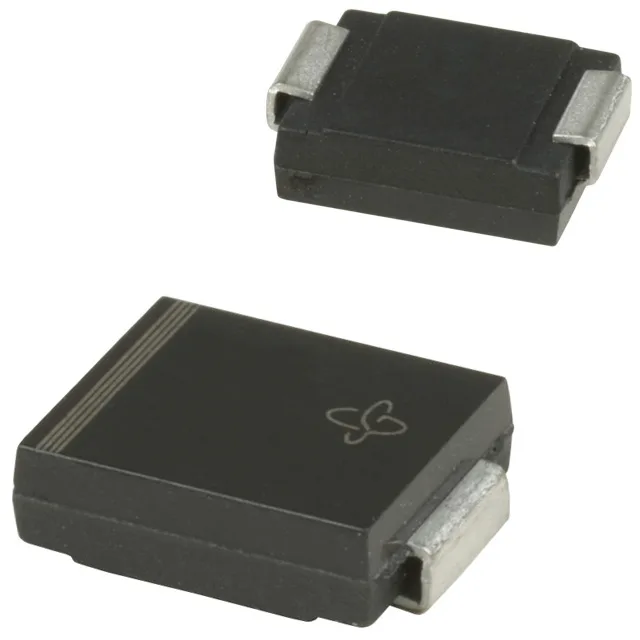
The 1.5SMC6.8A-M3/9AT: The 5.8 V reverse standoff rating sits below the 6.45 V minimum breakdown, so at normal operating voltage the device presents a high-impedance off-state and draws only leakage current. The gap between standoff and clamping (5.8 V to 10.5 V) is the protection window the designer works within. That waveform covers inductive load dumps and power-supply switching transients — the fault classes this series is sized for in general-purpose electronics. A shorter, sharper surge (8/20 µs) delivers the same peak current in less time, which compresses the absorbed energy into a narrower thermal spike; the datasheet derating curve handles that, but it is worth checking the application waveform against the test condition before committing the BOM line.
Thermal and package fit for board-level deployment
PCB pad geometry and copper area under the DO-214AB SMC leads set the thermal impedance from junction to ambient; undersized pads push the real-world Tj above what the rating implies. Surface-mount reflow profile follows standard SAC or lead-free solder schedules — no special handling required for assembly.