Which rail died — and can this part bring it back?
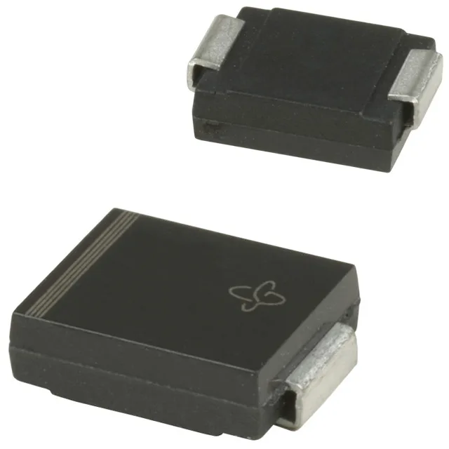
The scorch mark on the board tells you a rail got hit by a voltage transient — a spike that the clamping diode was supposed to absorb. The 1.5SMC6.8A-M3/57T is a unidirectional TVS diode rated to clamp at 10.5 V when the peak pulse current hits 143 A (10/1000 µs waveform). The reverse standoff voltage — the working voltage the rail sits at safely — is 5.8 V. That 5.8 V standoff / 10.5 V clamping spread is the headroom that determines whether this part survives the hit without letting the spike reach whatever is downstream. This is an A-suffix device, which marks it as unidirectional. A bidirectional TVS in the same SMCJ/1.5SMC package would be the non-A variant — swap one for the other and the polarity gets inverted on an AC-coupled rail. Know which direction your fault rail goes before you drop this onto the board.
Clamp budget — what 1500 W and 150 °C Tj actually mean for the layout
Repetitive pulses or a longer duration (8/20 µs is common in lightning-surge tests) will reduce the effective clamping capability below that headline number. The thermal impedance from junction to leads matters here: the DO-214AB package thermal pad lands directly on the copper pour, and a healthy pad width buys back some of that pulse-handling margin. Junction temperature runs from -65 °C to a maximum of 150 °C. The 150 °C ceiling is the limiting factor in confined enclosures without active cooling — if the board runs hot from adjacent components, the TVS derates before the peak pulse rating does. Budget the ambient and adjacent load dissipation into the thermal pad layout, not just the standoff voltage.