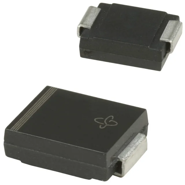
The 1.5SMC56CA-M3/57T: A 19.5 A peak pulse current at that waveform means the clamping voltage of 77 V is reached under a realistic IEC 61000-4-5 surge event, protecting downstream ICs and connectors from voltage overshoot. The difference between the 47.8 V reverse standoff and the 77 V clamping ceiling is the protection headroom the circuit designer trades off against let-through voltage tolerance. The three voltage gates — 47.8 V standoff (typ), 53.2 V minimum breakdown, 77 V clamping maximum at 19.5 A — must all sit correctly relative to the protected rail. The standoff voltage sets the DC working voltage the line can carry continuously without the TVS conducting; the breakdown voltage is where the diode begins to avalanche; the clamping voltage is the let-through at the rated surge current. For a 48 V nominal rail, 47.8 V standoff gives very little margin — a designer working to IEC 61000-4-5 Class 3 or higher should verify that transient suppressors upstream provide the needed differential.
TransZorb family and what the temperature range signals for deployment
The TransZorb® designation marks Vishay's original silicon-based transient voltage suppressor — it avalanche-clamps rather than crowbarring, which means it limits voltage without drawing the full surge current to ground as a short. That matters for circuits where the downstream load must survive the clamping event without a hard short. Surface-mount DO-214AB (SMC) package — the cathode bar connects directly to the thermal pad on the PCB, so the layout copper area under and around the TVS determines the thermal impedance to ambient. A diode that clamps a surge and survives the thermal transient needs that copper pour; under-designing the pad footprint is the most common reason these parts fail prematurely in the field.