Clamping a 300V rail in an automotive environment
The 1.5SMC350AHE3_ALL: With a 300V reverse standoff voltage and a 482V maximum clamping point at 3.1A, it protects a nominal 300V DC bus or 240V AC rectified rail from transients that would otherwise punch through downstream silicon.
What the clamping numbers mean for your BOM
The 300V reverse standoff is the maximum DC or peak AC voltage the TVS can sit across without conducting in normal operation. If your rail is a nominal 300V bus with 10% tolerance, the standoff gives you 30V of headroom before the diode starts leaking. The 482V clamp is the voltage the TVS forces the line to during a surge — anything downstream must survive that peak without avalanche breakdown. In practice, a real-world surge (e.g. a load-dump event on a 24V truck system stepped up through a DC-DC) will have a different waveshape, but the 1500W rating lets you scale: if your transient is 500µs wide, the part can absorb roughly 1.5x the peak current before the junction temperature limit is reached.
Package and board-fit for the DO-214AB
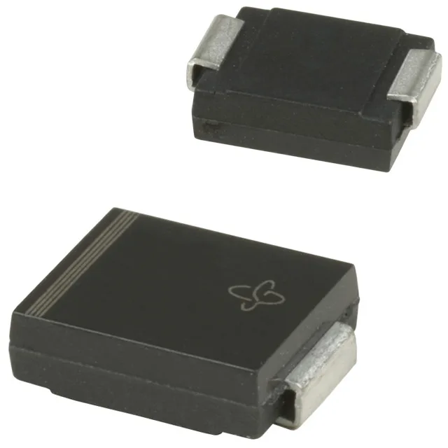
The supplier device package is listed as DO-214AB (SMCJ) — the JEDEC variation is the same copper leadframe, same pad layout. The cathode band on the body identifies the unidirectional orientation; the single-channel construction means it clamps only one polarity, so for AC lines you need back-to-back parts or a bidirectional variant. In a 105°C under-hood ambient, the effective pulse-handling drops to roughly 75% of the 1500W rating.
Sourced through independent distribution channels. No stock-holding claim — the part is quoted to order per RFQ.