Transient protection for a 24V rail
The 1.5SMC30A-E3/9AT: With a 28.5V minimum breakdown voltage and a 41.4V clamp at 36.2A (10/1000µs waveform), it sits between a standard 24V supply and the downstream circuitry — the standoff voltage is high enough to avoid nuisance clamping on normal ripple, yet the clamp triggers before the protected device's abs-max rating.
1500W peak pulse — what it means on a real board
That figure is the energy-handling ceiling for a single pulse — in a 24V industrial input or a 28V automotive bus, it absorbs the typical load-dump or inductive kickback transient without failing short. The 36.2A peak pulse current at the 41.4V clamp tells you the series impedance ahead of the diode must limit the surge below that level, or the part enters secondary breakdown. At the cold end, the breakdown voltage shifts upward slightly (positive temperature coefficient typical for Zener TVS); at 150°C, leakage current rises but the clamping voltage stays within the datasheet limits.
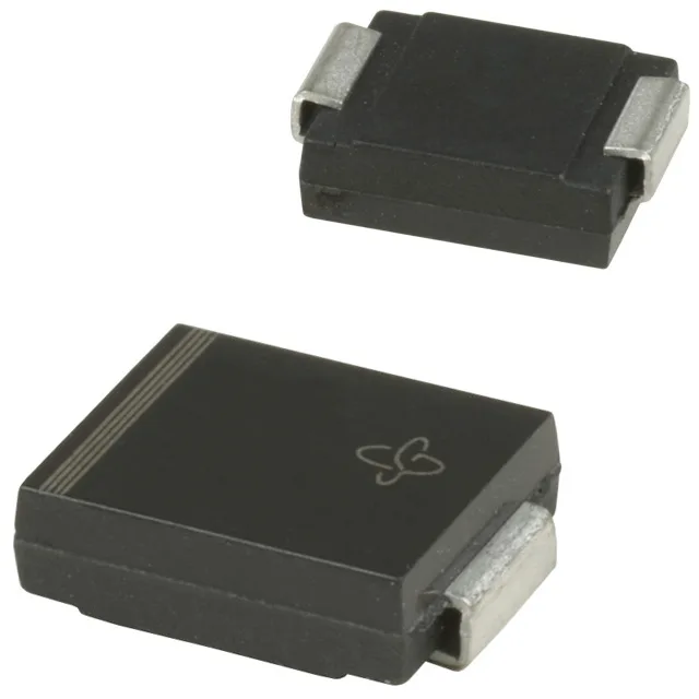
The body measures roughly 7.1 mm × 6.2 mm with a 2.6 mm height — standard for a 1500W TVS in this power class. Reflow soldering profile follows the JEDEC J-STD-020 moisture sensitivity level (MSL 1, no bake required before reflow). The cathode band marks the unidirectional orientation; the opposite end is the anode. Board layout should keep the TVS close to the protected IC or connector to minimize parasitic inductance between the clamp and the transient source.